A Jumper Flying Spot Scanning Device Used in X-ray Backscatter Imaging System

An imaging system, flying point scanning technology, applied in the direction of measuring devices, material analysis using wave/particle radiation, instruments, etc., can solve the problems of insufficient rigidity of the scanning drum, X-ray leakage, and inability to install, etc., to reduce leakage Effects of dose rate, increased occlusion ability, and reduced background value

Active Publication Date: 2017-11-21
CHINA INSTITUTE OF ATOMIC ENERGY
View PDF6 Cites 0 Cited by
  • Summary
  • Abstract
  • Description
  • Claims
  • Application Information

AI Technical Summary

Problems solved by technology

[0012] Aiming at the problems existing in the prior art, the purpose of the present invention is to provide a jumper flying spot scanning device for X-ray backscatter imaging system, which can solve the problem of cylindrical flying spot scanners due to the continuous penetration of the scanning drum. The rigidity of the scanning drum caused by this is insufficient, and other forms of X-ray scanners are too large to be installed in a small space, and there are problems such as X-ray leakage.

Method used


Image

  • A Jumper Flying Spot Scanning Device Used in X-ray Backscatter Imaging System
  • A Jumper Flying Spot Scanning Device Used in X-ray Backscatter Imaging System
  • A Jumper Flying Spot Scanning Device Used in X-ray Backscatter Imaging System

Examples


Embodiment Construction

[0043] The present invention will be further described below in conjunction with the accompanying drawings and specific embodiments.

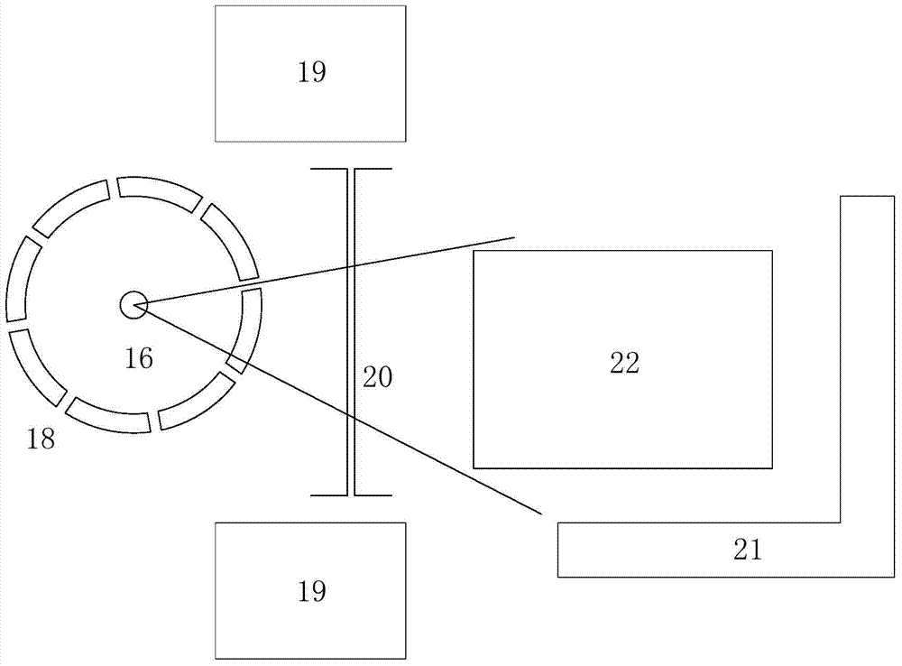
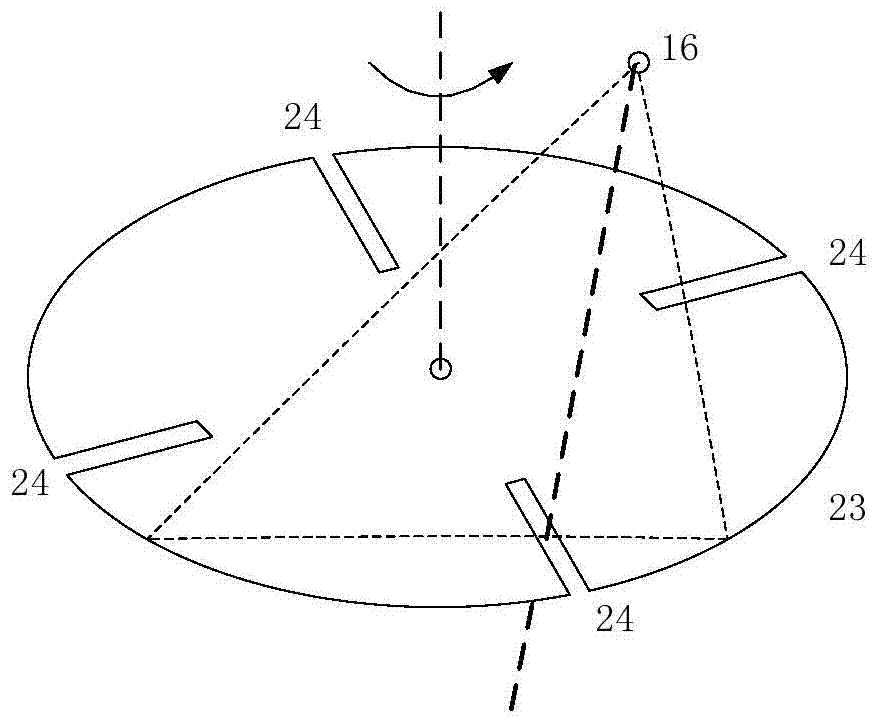
[0044] Such as Figure 9 A jumper flying spot scanning device for an X-ray backscatter imaging system is shown, including a ray source 16 located in the X-ray machine 1, and an incident collimator connecting the X-ray machine 1 and the scanner outer cylinder 4 2. The scanning drum 7 fixed in the outer cylinder 4 of the scanner through the rotating shafts 8 at both ends, and the exit collimator 3 connected with the outer drum 4 of the scanner, is characterized in that: the scanning drum 7 A number of discontinuous incident slit sections 11 and exit slit sections 12 are engraved on the side wall, which can be formed by one incident slit section 11 and one exit slit section 12 at any time when the scanning drum 7 rotates. The only scanning collimation hole. The outer cylinder 4 of the scanner is a hollow steel cylinder with uniform wall thicknes...


PUM


Abstract

The invention belongs to the field of radiation imaging detection equipment, and in particular relates to a jumper flying spot scanning device for an X-ray backscatter imaging system. Existing X-ray imaging detection devices have problems such as X-ray leakage, large scanning mechanism and poor rigidity, which are not suitable for installation in narrow spaces, low spatial resolution of point scanning, and poor signal-to-noise ratio. The scanning device according to the present invention comprises a ray source located in the X-ray machine, an incident collimator connecting the X-ray machine and the scanner outer cylinder, and a scanning drum fixed in the scanner outer cylinder through the rotating shafts at both ends. , an exit collimator connected to the outer cylinder of the scanner, characterized in that: the side wall of the scanning cylinder is penetratingly engraved with several discontinuous entrance slit sections and exit slit sections, which can pass through an incident slit section at any time when the scanning cylinder rotates. The slit segment and an exit slit segment relatively constitute the only scanning collimation hole. It has the advantages of small size, high rigidity of the scanning drum, less X-ray leakage and high spatial resolution.

Description

technical field [0001] The invention belongs to the field of radiation imaging detection equipment, and in particular relates to a jumper flying spot scanning device for an X-ray backscatter imaging system. Background technique [0002] The device involved in the present invention is mainly used to generate linear X-ray beams to realize periodic one-dimensional line scanning in a certain fixed direction, and to realize two-dimensional scanning by moving in a direction perpendicular to the line scanning direction by other mechanical devices. [0003] Traditional X-ray inspection systems are used in cargo inspection at airports, seaports, and land checkpoints, as well as inspection of packages and luggage carried by people in public places. A typical system based on X-ray transmission energy absorption detection is a transmission imaging system, which usually uses a fan-shaped ray beam emitted by an X-ray machine, and a line detector obtains the transmitted X-ray energy data t...

Claims


Application Information

Patent Timeline
Patent Type & Authority Patents(China)
IPC IPC(8): G01N23/203
Inventor 张炜王强王国宝
Owner CHINA INSTITUTE OF ATOMIC ENERGY
Why Eureka
Try Eureka