Double chamber liquid photochromic glasses

A technology of color-changing glasses and cavity, applied in glasses/goggles, optics, instruments, etc., can solve the problems of cumbersome production process, high cost, large flow resistance, etc., and achieve strong controllability, reduce residues, and reduce costs. Effect

Active Publication Date: 2017-06-30
HARBIN INST OF TECH
View PDF5 Cites 1 Cited by
  • Summary
  • Abstract
  • Description
  • Claims
  • Application Information

AI Technical Summary

Problems solved by technology

[0004] In order to solve the problems of slow discoloration speed, single discoloration, inability to realize manual control based on user's wishes, and poor controllability of solid color-changing glasses, and to solve the problems of cumbersome production process, high cost, large liquid residue and relatively low flow resistance of micro-channel liquid color-changing glasses To solve such problems, the present invention provides a kind of double-layer chamber type liquid photochromic glasses

Method used


Image

  • Double chamber liquid photochromic glasses
  • Double chamber liquid photochromic glasses
  • Double chamber liquid photochromic glasses

Examples


specific Embodiment approach 1

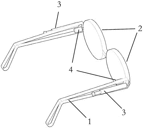
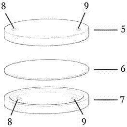
[0024] Specific implementation mode one: combine figure 1 and image 3 Explain that the color-changing glasses include a frame 1, two lenses 2, two colorless fluid (liquid / gas) actuators 3, two elastic colored fluid storage chambers 4, colorless fluid chambers 5, elastic films 6 and colored The fluid chamber 7 is composed. Two lenses 2 are arranged in the frame 1, two colorless fluid actuators 3 are installed on the outside of the two temples of the frame 3, and two colored fluid storage chambers 4 are installed on the inside of the two temples. The colorless fluid actuator 3 is two manual pistons, the cavity is filled with colorless fluid (liquid / gas), and the elastic colored fluid storage chamber 4 stores colored fluid. The inside of the lens 2 is composed of a colorless fluid chamber 5, a colored fluid chamber 7 and an elastic film 6, and the three parts are assembled together to form an eyeglass. The colorless fluid actuator 3 is connected to the colorless fluid chamber...

specific Embodiment approach 2

[0025] Specific implementation mode two: combination figure 1 Note that the depth of the colorless fluid chamber 5 is 1-2 mm, and the depth of the colored fluid chamber 7 is 0.05-1 mm. Other components and connections are the same as those in the first embodiment.

specific Embodiment approach 3

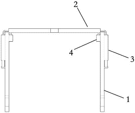
[0026] Specific implementation mode three: combination figure 2 Explain that the colorless fluid actuator 3 is two diaphragm chambers, which are installed on the two corners of the mirror frame 1 . The diaphragm cavity is connected with the colorless fluid cavity 5 in the lens 2 . When the diaphragm is pressed, the colorless fluid in the diaphragm chamber is pushed into the colorless fluid chamber 5 on the lens 2 . Other components and connections are the same as those in the first embodiment.


PUM


Abstract

A double-chamber liquid color-changing glasses, including a frame, lenses, colorless fluid actuator, colored fluid, colorless fluid, elastic film, colorless fluid chamber, colored fluid chamber and elastic colored fluid storage chamber, lens The inside is composed of a colorless fluid chamber, a colored fluid chamber and an elastic film, and the colorless fluid chamber and the colored fluid chamber are separated by an elastic film; the colorless fluid actuator is installed on the two temples of the frame On the outside, the colorless fluid is stored in the colorless fluid actuator, and the colorless fluid actuator is connected to the colorless fluid chamber through a pipeline; the elastic colored fluid storage chamber is installed on the inner side of the two mirror legs of the frame, and the colored fluid is stored in the In the elastic colored fluid storage cavity, the elastic colored fluid storage cavity is connected with the colored fluid cavity through a pipeline. The invention controls the circulation of the colored fluid between the lens and the storage cavity by deforming the film through the pressure change of the colorless fluid in the cavity so as to change the color of the lens.

Description

technical field [0001] The invention relates to liquid color-changing glasses with double-layer cavity. Background technique [0002] At present, the color-changing glasses on the market mainly use solid color-changing materials, and these materials show different structural states under different light intensities. For example, silver bromide, when the light is strong, the silver bromide will decompose into bromine and silver particles, making the lens appear a darker color and protecting eyesight; and when the ambient light is weak, bromide ions And silver ions will synthesize silver bromide under the action of catalyst copper oxide, and restore the original transparent color of the lens. However, the main disadvantages of this solid photochromic mirror are: (1) The discoloration speed of the solid photosensitive material is relatively slow; (2) It is difficult to completely return to the original transparent color after the discoloration is completed; (3) The discolorati...

Claims


Application Information

Patent Timeline
Patent Type & Authority Patents(China)
IPC IPC(8): G02C7/10
CPCG02C7/105
Inventor 李松晶张敏蔡申
Owner HARBIN INST OF TECH
Why Eureka
Try Eureka