Brake rotor fixing mechanism and installation method thereof

A technology of brake rotor and fixing mechanism, which is applied in the direction of brake actuator, manufacturing motor generator, electromechanical device, etc., can solve the problems of increased processing and installation procedures, axial movement, low reliability, etc., and achieves good application prospects , high reliability and low cost

Inactive Publication Date: 2015-07-08
NANJING KANGNI MECHANICAL & ELECTRICAL
View PDF8 Cites 4 Cited by
  • Summary
  • Abstract
  • Description
  • Claims
  • Application Information

AI Technical Summary

Problems solved by technology

[0003] The technical problem solved by the present invention is the traditional way of fixing the motor shaft and the brake, which has low reliability and the risk of axial movement, and needs to process the keyway structure, increasing the processing and installation process, and the problem of high cost

Method used


Image

  • Brake rotor fixing mechanism and installation method thereof
  • Brake rotor fixing mechanism and installation method thereof
  • Brake rotor fixing mechanism and installation method thereof

Examples


Embodiment Construction

[0031] The present invention will be further described below in conjunction with the accompanying drawings.

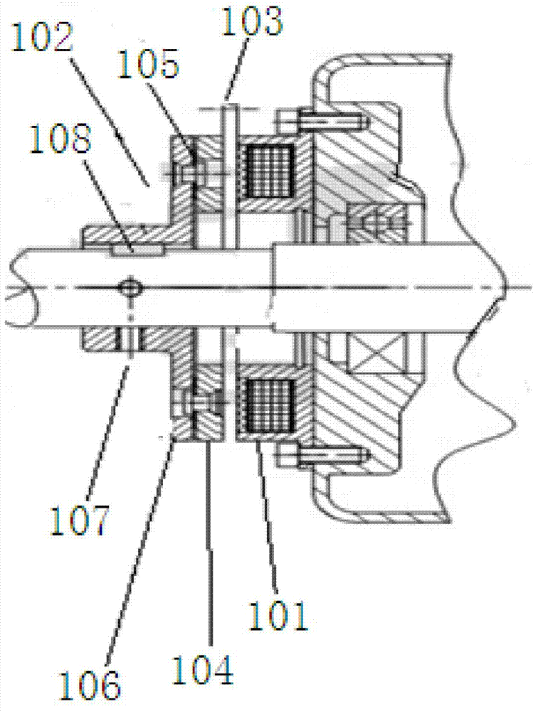
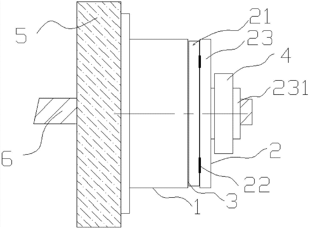
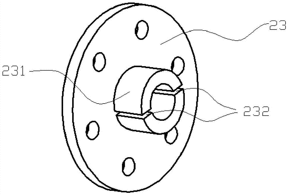
[0032] like figure 2 As shown, a brake rotor fixing mechanism includes a stator 1 fixed on the motor end cover by bolts, and a rotor 2 integrally formed with the motor shaft 6, the stator 1 and the rotor 2 are coaxially installed, and the rotor 2 Located on the outside of the stator 1, an axial gap 3 is provided between the stator 1 and the rotor 2. The rotor 2 includes an armature 21, a spring leaf 22, a flange 23 and a fastening ring 4. The armature 21 and the stator 1 The outer side of the flange 23, the spring piece 22 is arranged between the outer side of the armature 21 and the inner side of the flange 23, the flange boss 231 on the outer side of the flange 23 is socketed with the motor shaft 6, and the flange boss 231 There is an opening groove 232 on the top, and the fastening ring 4 is sleeved on the flange boss 231 to squeeze the flange boss 231 to deform a...


PUM


Abstract

The invention discloses a brake rotor fixing mechanism and an installation method thereof. The mechanism comprises a stator fixed to an end cover of a motor through a bolt, and a rotor connected with a motor shaft in an integrally formed mode, wherein the stator and the rotor are coaxially installed, the rotor is located on the outer side of the stator, an axial gap is reserved between the stator and the rotor, the rotor comprises an armature, a leaf spring, a flange and a fastening ring, the armature is located on the outer side of the stator, the leaf spring is arranged between the outer side of the armature and the inner side of the flange, a flange boss on the outer side of the flange is connected with the motor shaft in a sleeving mode, an open groove is formed in the flange boss, and the fastening ring is connected to the flange boss in a sleeving mode to squeeze and deform the flange boss so as to clamp the motor shaft. According to the brake rotor fixing mechanism and the installation method thereof, axial movement is avoided, structure is simple, installation is easy, reliability is high, cost is low, the mechanism can be used under positive and negative impact and in a high-vibration environment, and application prospects are broad.

Description

technical field [0001] The invention relates to the technical field of brake fixing, in particular to a brake rotor fixing mechanism and an installation method thereof. Background technique [0002] At present, the fixing method of the motor shaft and the brake is mainly a jackscrew plus a keyway structure, such as figure 1 As shown, the structure of the brake includes a stator 101, a rotor 102, an air gap 103, an armature 104, a spring leaf 105, a flange 106, a top screw 107, and a keyway 108. The motor shaft and the brake are matched through the top screw 107 and the keyway 108. Fixed, this conventional fixed structure has low reliability and is not suitable for positive and negative impact and high vibration environments, and there is a risk of axial movement, low reliability, not suitable for positive and negative impact and high vibration environments, and , it is necessary to process the keyway structure, increase the processing and installation process, and the cost ...

Claims


Application Information

Patent Timeline
Patent Type & Authority Applications(China)
IPC IPC(8): H02K7/102H02K15/00F16D65/14F16D121/24
CPCH02K7/10F16D65/14F16D2121/24H02K15/00H02K2213/03
Inventor 唐成文张伟尹琨禹浩诺
Owner NANJING KANGNI MECHANICAL & ELECTRICAL
Why Eureka
Try Eureka