Loudspeaker magnetic circuit structure

A loudspeaker and magnetic circuit technology, which is applied in the field of loudspeakers, can solve the problems of increasing the thickness of the loudspeaker, difficulty in increasing the magnetic flux, and difficulty in obtaining the shape, etc., to achieve the effect of increasing the B value of the magnetic flux, increasing the B value of the magnetic flux, and solving the effect of large magnetic flux leakage

Inactive Publication Date: 2015-07-08
GUOGUANG ELECTRIC +1
View PDF6 Cites 2 Cited by
  • Summary
  • Abstract
  • Description
  • Claims
  • Application Information

AI Technical Summary

Problems solved by technology

Therefore, the current speaker needs to increase the thickness of the main magnet and the secondary magnet to reduce the magnetic flux leakage, otherwise the magnetic flux will be difficult to increase and the speaker will be seriously distorted.
However, increasing the thickness of the main magnet and the auxiliary magnet will lead to an increase in the overall thickness of the speaker, making it difficult to obtain a product with a small shape and a thin thickness, which cannot meet the demand

Method used


Image

  • Loudspeaker magnetic circuit structure
  • Loudspeaker magnetic circuit structure
  • Loudspeaker magnetic circuit structure

Examples


Embodiment 1

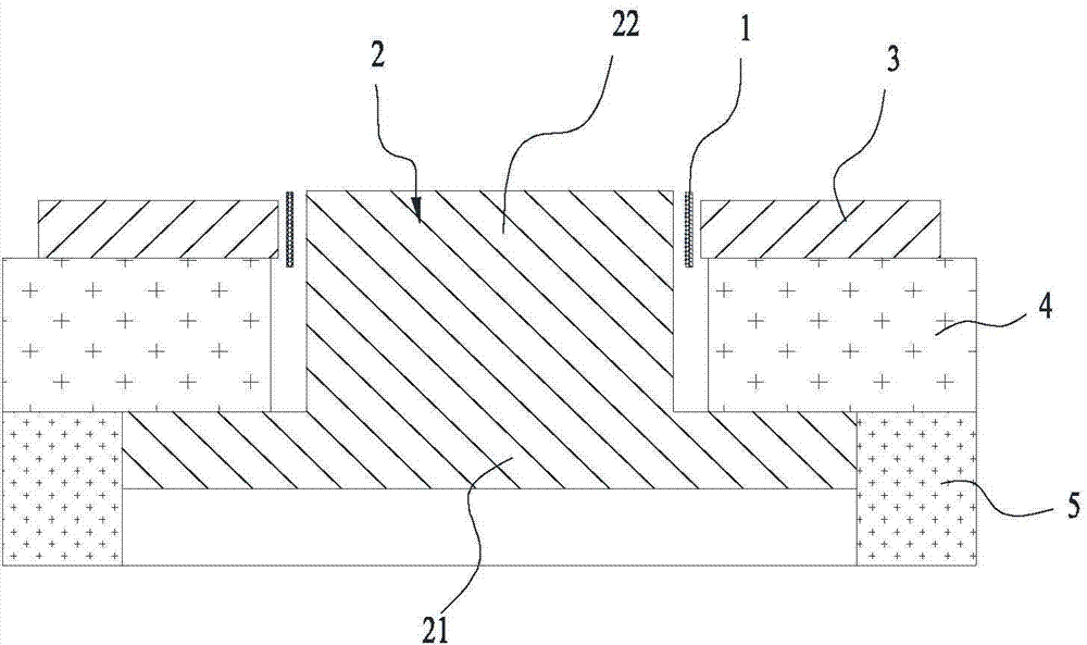
[0033] Such as figure 2 A loudspeaker magnetic circuit structure shown includes a voice coil 1, a T iron 2, a front splint 3, a main magnetic steel 4 and a first side magnetic steel 5, and the T iron 2 has a bottom plate 21 and a vertically protruding from the bottom plate 21. The cylinder 22, the main magnet 4, the front splint 3 and the voice coil 1 are all looped around the periphery of the cylinder 22, the main magnet 4 is stacked on the top surface of the bottom plate 21, the front splint 3 is stacked on the top surface of the main magnet 4; the voice coil 1 It is located between the socket of the front splint 3 and the outer wall of the cylinder 22, and a magnetic gap is formed between the voice coil 1 and the front splint 3 and the outer wall of the cylinder 22 respectively; The first side magnetic steel 5 is in close fit or clearance fit with the lower surface of the main magnetic steel 4 .

[0034] The main magnetic steel 4 is the main magnetic energy provider in th...

Embodiment 2

[0039] Such as Figure 4 Shown is Embodiment 2 of a loudspeaker magnetic circuit structure of the present invention. The differences between Embodiment 2 and Embodiment 1 are:

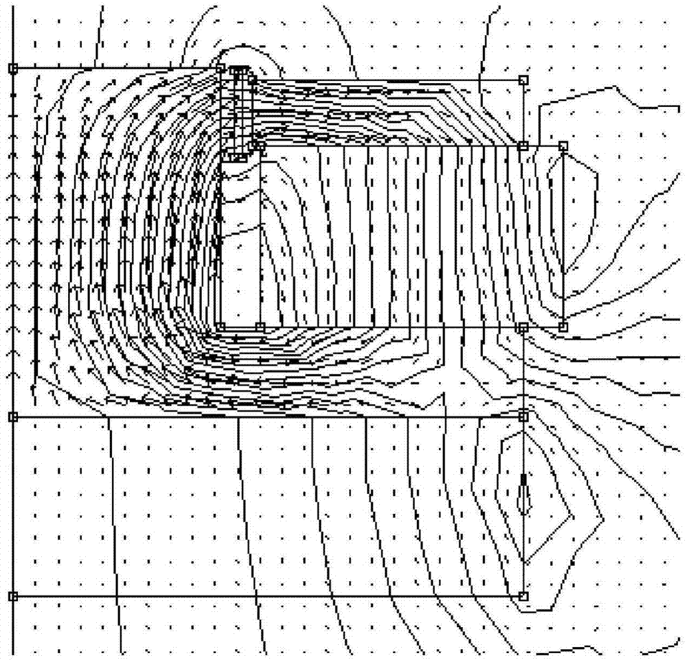
[0040] A first auxiliary magnet 6 is provided on the lower surface of the bottom plate 21 , and the first auxiliary magnet 6 closely fits or has a clearance fit with the inner wall of the pocket of the first side magnet 5 . The function of the first secondary magnet 6 is to increase the magnetic flux of the magnetic circuit, and at the same time, the first side magnet 5 can also reduce the magnetic flux leakage of the first secondary magnet 6 . The magnetic direction of each component after adding the first auxiliary magnetic steel 6 is as follows: Figure 8 As shown, the magnetic orientation of each component can also be as Figure 8 Contrary to what is shown in .

[0041] If the first secondary magnetic steel 6 is lower than the first side magnetic steel 5, the speaker can be made thinner as a who...

Embodiment 3

[0044] Such as Figure 9 Shown is Embodiment 3 of a loudspeaker magnetic circuit structure of the present invention. The difference between Embodiment 3 and Embodiment 2 is:

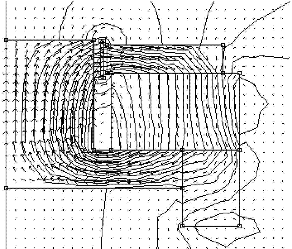
[0045] The top surface of the cylinder 22 is provided with a second secondary magnetic steel 7, which is located in the top surface of the cylinder 22, to avoid affecting the magnetic gap formed between the T iron 2 and the main magnetic steel 4, the second The auxiliary magnetic steel 7 can increase the magnetic flux, and can further reduce the flux leakage between the T iron 2 and the main magnetic steel 4 . The second secondary magnetic steel 7 is all round or rectangular, or other arbitrary polygonal shapes, and the circular or rectangular shape is better for increasing the magnetic flux B, and its magnetic field line circuit diagram is as follows Figure 10 shown.


PUM


Abstract

The invention discloses a loudspeaker magnetic circuit structure. The magnetic circuit structure comprises a voice coil, T iron, a front clamp plate, main magnetic steel and first side magnetic steel. The T iron is provided with a base plate and a column perpendicularly extending from the base plate. The periphery of the column is sleeved with the main magnetic steel, the front clamp plate and the voice coil. The main magnetic steel is stacked on the top surface of the base plate, and the front clamp plate is stacked on the top surface of the main magnetic steel. The voice coil is located between a muzzle bell of the front clamp plate and the outer wall of the column, and magnetic gaps are formed between the voice coil and the front clamp plate as well as between the voice coil and the outer wall of the column respectively. The periphery of the base plate is sleeved with the first side magnetic steel, and the first side magnetic steel is in wringing fit or clearance fit with the lower surface of the main magnetic steel. According to the loudspeaker magnetic circuit structure, flux leakage can be reduced, and the magnetic flux of the magnetic circuit magnetic gaps is enhanced. Meanwhile, the height of the magnetic circuit structure is reduced, so a loudspeaker can be made to be smaller, thinner and lower in cost.

Description

technical field [0001] The invention relates to the field of loudspeakers, in particular to a loudspeaker magnetic circuit structure. Background technique [0002] With the advancement of science and technology and the continuous improvement of market demand, the sound quality requirements of the audio system are also continuously improved, especially the small multimedia system is more popular. These require the speaker to have good performance, small shape, and thin thickness. [0003] To make the speaker have good performance, one of the ways is to increase the BL value of the speaker (that is, the magnetic field strength of the coil gap) as much as possible within a reasonable cost. At present, the traditional loudspeaker magnetic circuit structure includes the T-iron shown, the voice coil, the front splint, the main magnet and the auxiliary magnet. Magnetic flux leakage occurs between steel and T iron, and its magnetic field lines are as follows: figure 1 shown in th...

Claims


Application Information

Patent Timeline
Patent Type & Authority Applications(China)
IPC IPC(8): H04R9/02
Inventor 钟柳强
Owner GUOGUANG ELECTRIC
Why Eureka
Try Eureka