Piping joint

A piping and pipe body technology, applied in the direction of pipe/pipe joint/pipe fitting, pipe connection arrangement, threaded connection, etc., can solve problems such as the adverse effect of the watertight performance of the pipe joint, and achieve the effect of inhibiting leakage and inhibiting separation

Active Publication Date: 2015-07-08
BRIDGESTONE CORP
View PDF4 Cites 1 Cited by
  • Summary
  • Abstract
  • Description
  • Claims
  • Application Information

AI Technical Summary

Problems solved by technology

If an excessive tightening torque is applied to such a piping joint, the metal pipe and the resin pipe will separate from each other, causing a fear of adversely affecting the watertight performance of the piping joint

Method used


Image

  • Piping joint
  • Piping joint
  • Piping joint

Examples


no. 2 approach

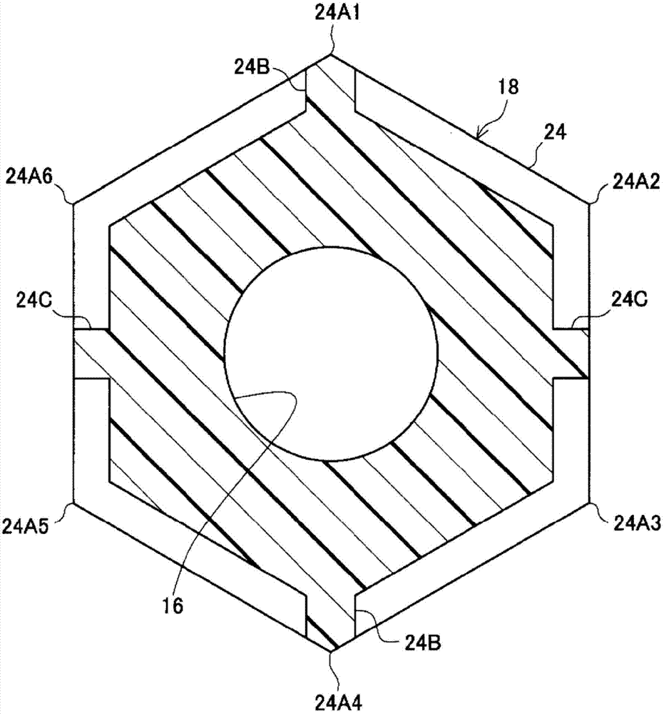
[0058] Next, a piping joint 30 according to a second exemplary embodiment will be described. The same configurations as those of the first exemplary embodiment are assigned the same reference numerals, and descriptions thereof are omitted. Such as Figure 9 As shown, in the pipe joint 30 according to the present exemplary embodiment, the rib 32B is formed at all six corners 32A1 to 32A6 of the annular protrusion 32 constituting the first hexagonal portion 31 . Other configurations are the same as those of the first exemplary embodiment.

[0059] In the pipe joint 30 according to the present exemplary embodiment, the rib 32B is formed on all six corners 32A1 to 32A6 of the annular protrusion 32 so that all the corners 32A1 to 32A6 obtain equal strength. Accordingly, when gripping the first hexagonal portion 31 with the wrench 200 , there is no need to consider the position of the rib 32B.

[0060]

[0061] Next, a pipe joint 50 according to a third exemplary embodiment wil...


PUM


Abstract

Provided is a piping joint (10) comprising: a metal pipe (12) that can be screwed into a pipe body; a resin pipe (14) having one end section that is configured to be connectable with another pipe body and another end section that is integrally formed with the metal pipe (12); and a first polygonal section (18) that is provided to the outer peripheral surface of the resin pipe (14) and that comprises a corner section (24A) that requires less torque to break than the amount of torque required to separate the metal pipe (12) and the resin pipe (14).

Description

technical field [0001] The present invention relates to a pipe joint. Background technique [0002] Among pipe fittings for joining pipe bodies together, there is known a pipe fitting having a resin pipe and a metal pipe integrally formed by insert molding (insert molding). If an excessive tightening torque is applied to such a pipe joint, the metal pipe and the resin pipe will separate from each other, raising a fear of adversely affecting the watertight performance of the pipe joint. [0003] The pipe connection structure described in Japanese Patent Laid-Open No. 2009-115192 is provided with a hexagonal portion for being held by a tool on the outer peripheral surface, and is formed with slits extending radially inward from each corner of the hexagonal portion. It is desirable to adopt such a pipe connection structure on a metal pipe, the hexagon cannot be rotated because the corner of the hexagon which has been weakened by the slit is crushed, and the resin pipe is not m...

Claims


Application Information

Patent Timeline
IPC IPC(8): F16L19/02
CPCF16L15/00F16L47/24F16B31/027
Inventor 饭塚建郎
Owner BRIDGESTONE CORP
Why Eureka
Try Eureka