A pole part of a medium voltage circuit breaker arrangement comprising a triggered gap unit

A technology for triggering gap and pole components, which is used in high-voltage air circuit breakers, electrical components, overvoltage arresters using spark gaps, etc.

Inactive Publication Date: 2015-07-08
ABB TECH AG
View PDF5 Cites 6 Cited by
  • Summary
  • Abstract
  • Description
  • Claims
  • Application Information

AI Technical Summary

Problems solved by technology

However, for high-performance applications combining capacitive switching capability and short-circuit current breaking capability, the above-mentioned technical problems will arise

Method used


Image

  • A pole part of a medium voltage circuit breaker arrangement comprising a triggered gap unit
  • A pole part of a medium voltage circuit breaker arrangement comprising a triggered gap unit

Examples


Embodiment Construction

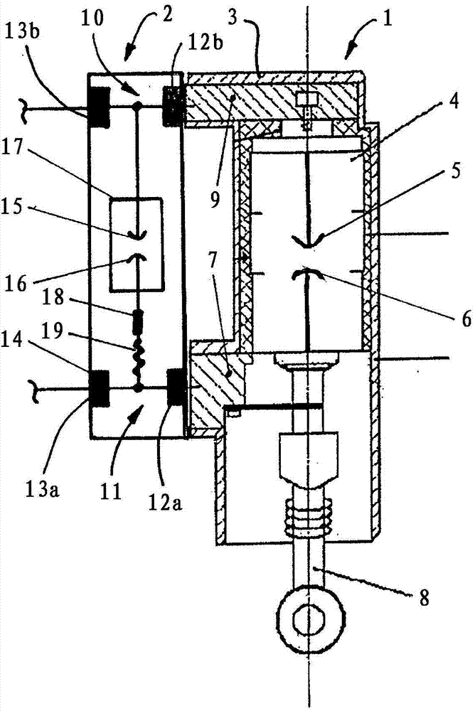
[0019] according to figure 1 , a medium voltage circuit breaker device usually consists of a pole part 1 and a vacuum trigger gap or spark trigger gap (or multi-gap) unit 2. It is possible to provide a multi-gap configuration consisting of a series connection of vacuum gap and gas gap or as described above as a vacuum or gas multi-gap configuration. A vacuum-triggered gap and / or spark-triggered gap (multi-gap) unit 2 is arranged adjacent to the pole part 1 as an auxiliary device.

[0020] The pole part 1 comprises a pole housing 3 made of epoxy resin or thermoplastic material for accommodating a vacuum interrupter 4 . The vacuum interrupter 4 contains a corresponding pair of electrical contacts 5 and 6 . The stationary electrical contact 5 is connected to an upper electrical terminal 9 molded in the pole housing 3 . The opposite movable electrical contact 6 is connected to the lower electrical terminal 7 of the pole housing 3 and is operated by a push rod 8 in order to inte...


PUM


Abstract

A pole part (1) of a low-, medium- or high voltage circuit breaker arrangement comprising a pole housing (3) for accommodating a vacuum interrupter (4) with a pair of corresponding electrical contacts (5, 6), wherein a fixed electrical contact (5) is connected to an upper electrical terminal (9) and a movable electrical contact (6) is connected to a lower electrical terminal (7) and operated by a pushrod (8), and a triggered -vacuum gap or -gas gap or the combination of gas and vacuum gap connected in sereies unit (2) is parallel connected to the electrical contacts (5, 6) in order to avoid contacts welding, wherein the triggered vacuum gap or gas gap unit (2) is removable mounted between the upper electrical terminal (9) and the lower electrical terminal (7) arranged adjacent to the pole housing (3). Furthermore there is the possibility to trigger directly the vacuum interrupter device to get a similar effect to protect the vacuum interrupter device from inrush current load during the closing operation especially during capacitive switching.

Description

technical field [0001] The invention relates to a pole part of a low-voltage, medium-voltage or high-voltage circuit breaker device, said pole part comprising a pole housing for accommodating a vacuum interrupter with a pair of corresponding electrical contacts, wherein the electrical contacts The head is connected with the upper electric terminal, and the movable electric contact is connected with the lower electric terminal on the pole shell and operated by the push rod. An encapsulated trigger gap unit (vacuum gap or pressurized gap unit) is connected in parallel with the electrical contacts in order to avoid contact welding during capacitive switching operation (contact welding here takes inrush current during closing operation), avoiding under vacuum atmosphere "Spot welding contact system". Background technique [0002] Circuit breaker arrangements with vacuum interrupter inserts accommodated in corresponding pole parts are generally used in the low-, medium- and high...

Claims


Application Information

Patent Timeline
Patent Type & Authority Applications(China)
IPC IPC(8): H01H9/14H01T4/08H01H33/66H01H33/59
CPCH01H33/59H01H9/14H01T4/08H01H33/6606H01H9/02H01H33/045
Inventor D·根奇T·拉马拉
Owner ABB TECH AG
Why Eureka
Try Eureka