
A high-strength aluminum alloy high-thickness ratio net-shape isothermal forging die
An isothermal forging, aluminum alloy technology, applied in manufacturing tools, metal processing equipment, forging/pressing/hammer devices, etc., can solve the problems of small high-to-thickness ratio, difficult to form high-to-thickness ratio forgings, poor high temperature fluidity, etc.
- Summary
- Abstract
- Description
- Claims
- Application Information
AI Technical Summary
Problems solved by technology
Method used
Image

Examples
Embodiment 17075
[0022] Example 1 7075 aluminum alloy forging die
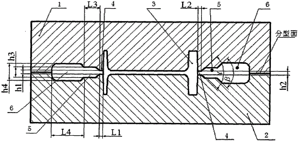
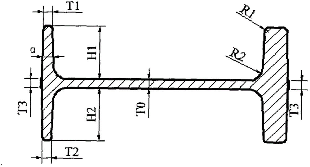
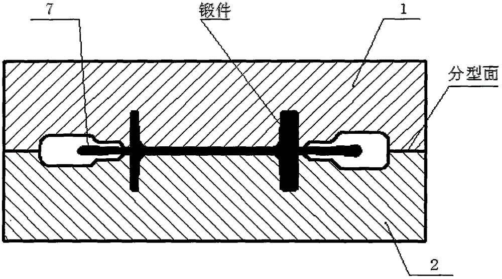
[0023] Such as figure 1 , figure 2 , image 3 and Figure 4 As shown, the 7075 aluminum alloy forging die includes an upper die 1, a lower die 2, and a forging cavity 3 located between the upper die 1 and the lower die 2, and an overflow cavity is arranged between the upper die 1 and the lower die 2, and the overflow The material chamber is composed of three areas, namely the damping control zone 4, the damping release area 5 and the overflow storage chamber 6. The heights of the three partitions of the overflow cavity are respectively: h1=h2=1.2mm, h3=6mm, h4=10mm. The width of each area of the overflow chamber meets the following requirements: L1=L2=1.5mm, L3=9mm, L4=19mm. The overflow chamber has two height transition steps with included angles β and γ, γ=60°, β=90°. The h1 and h2 are the heights of the left and right damping control bands 4 respectively, h3 is the height of the damping release zone 5, h4 is the he...
Embodiment 22024
[0025] Example 2 2024 aluminum alloy forging die
[0026] Such as Figure 5 As shown, a 2024 aluminum alloy forging die includes an upper die 1, a lower die 2, and a forging cavity 3 between the upper die 1 and the lower die 2, and an overflow cavity is arranged between the upper die 1 and the lower die 2, and the overflow The material chamber is composed of three areas, namely the damping control zone 4, the damping release area 5 and the overflow storage chamber 6. The heights of the three partitions of the overflow cavity are respectively: h1=h2=1.5mm, h3=6mm, h4=10. The width of each area of the overflow cavity is: L1=L2=1.8mm, L3=14mm, L4=27mm. The overflow chamber has two height transition step angles β and γ, the values of which are respectively: γ=60°, β=90°. The h1 and h2 are the heights of the left and right damping control bands 4 respectively, h3 is the height of the damping release zone 5, h4 is the height of the overflow storage chamber 6, and L1 and L2 ar...
Embodiment 36061
[0028] Example 3 6061 aluminum alloy forging die
[0029] Such as Figure 6 As shown, the 6061 aluminum alloy forging die includes an upper die 1, a lower die 2, and a forging cavity 3 between the upper die 1 and the lower die 2, and an overflow cavity is arranged between the upper die 1 and the lower die 2, and the overflow The material chamber is composed of three areas, namely the damping control zone 4, the damping release area 5 and the overflow storage chamber 6. The heights of the three partitions of the overflow cavity are respectively: h1--h2=1.5mm, h3=4mm, h4=10. The width of each area of the overflow cavity is: L1=L2=1.5mm, L3=13mm, L4=28mm. The overflow chamber has two height transition step angles β and γ, the values of which are respectively: γ=60°, β=90°. The h1 and h2 are the heights of the left and right damping control bands 4 respectively, h3 is the height of the damping release zone 5, h4 is the height of the overflow storage chamber 6, and L1 and L2...
PUM
 Abstract
Description
Claims
Application Information