
An automatic feeding and cutting machine for metal bars

A technology of automatic feeding and metal rods, which is applied in metal sawing equipment, metal processing machinery parts, metal processing, etc., can solve the problems of high labor cost, unsuitable for cost saving of enterprises, and low production efficiency, so as to reduce labor intensity, The effect of facilitating automated production

Inactive Publication Date: 2017-06-09
CHANGHONG PRECISION TOOL DONGGUAN CO LTD
View PDF6 Cites 1 Cited by
  • Summary
  • Abstract
  • Description
  • Claims
  • Application Information

AI Technical Summary

Problems solved by technology

[0003] From the above description of the production process, it can be seen that the traditional metal bar cutting method has low production efficiency, labor-intensive workers and is not safe.
Moreover, in the process of manual operation, the quality of all products cannot be guaranteed to meet the standard
In particular, it is very difficult to rework the metal bars that are cut into shorter lengths. The general treatment method is to melt them directly, which wastes casting costs.
[0004] From the perspective of production efficiency, the traditional cutting method requires more than one worker to take care of one cutting equipment, and the labor cost is obviously too high, which does not meet the cost-saving requirements of the enterprise.

Method used


Image

  • An automatic feeding and cutting machine for metal bars
  • An automatic feeding and cutting machine for metal bars
  • An automatic feeding and cutting machine for metal bars

Examples


Embodiment Construction

[0027] The present invention will be described in further detail below in conjunction with the accompanying drawings.

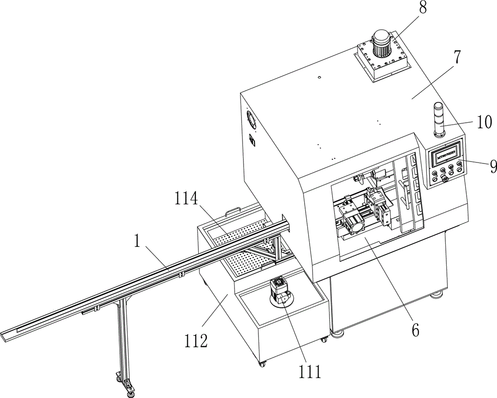
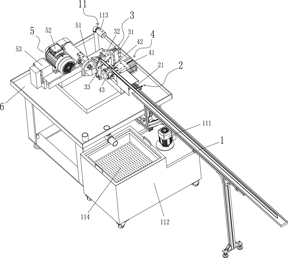
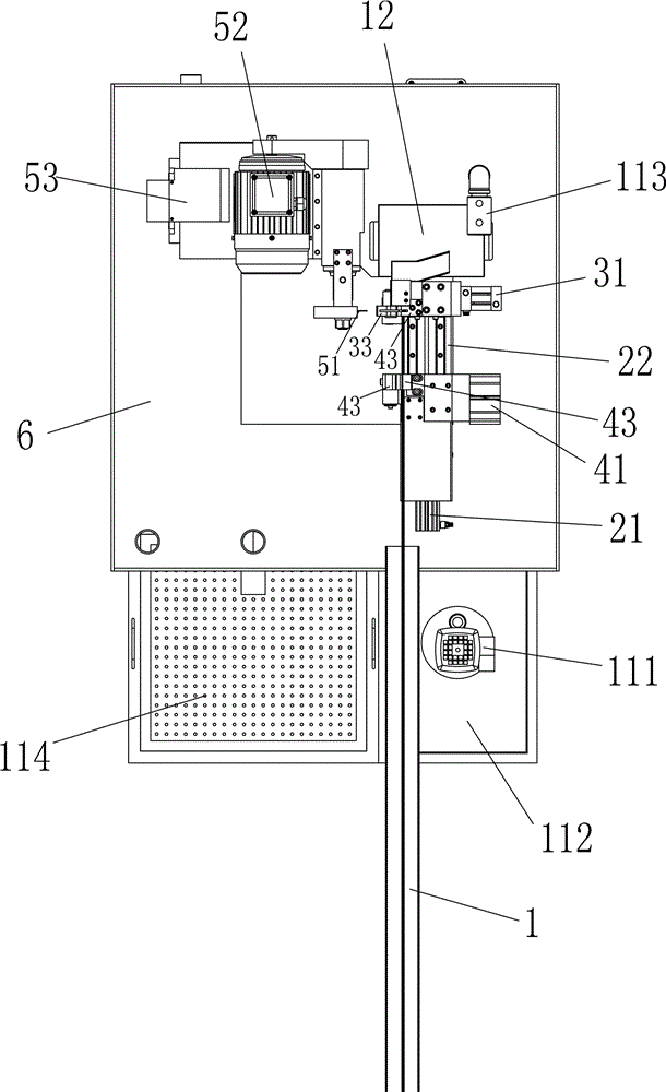
[0028] Such as figure 1 , 2 , 3, 4, and 5 show an automatic feeding and cutting machine for a metal bar, including an automatic feeding mechanism and an automatic cutting mechanism 5, the metal bar is placed on the rack 1, and one end of the metal bar is inserted into the automatic In the feeding mechanism, the first cutting position is manually set in the automatic feeding mechanism. After the first cutting, the cut is the material head, which needs to be removed; after the material head is removed, start the automatic positioning mode, and pass the automatic feeding mechanism. Adjust the position of the metal bar, and finally position the subsequent cutting position of the metal bar, and so on; the automatic cutting mechanism 5 starts after the metal bar is positioned successfully and cuts the metal bar in the automatic feeding mechanism.

[0029] Further...


PUM


Abstract

The invention discloses an automatic feeding and cutting machine for metal bars, which includes an automatic feeding mechanism and an automatic cutting mechanism; wherein, the automatic feeding mechanism includes a feeding device and a clamping device, and the feeding device controls the clamping device to adjust the position , so as to locate the cutting position of the metal bar in the clamping device; the automatic cutting mechanism includes a saw blade, a first motor that controls the rotation of the saw blade, and a second motor that controls the advance and retreat of the saw blade to the metal bar. motor. The invention can automatically complete the feeding and cutting of the ultra-long metal bar, improves the production efficiency and product quality, saves the cost of the enterprise, reduces the labor intensity of the workers and improves the safety.

Description

technical field [0001] The invention relates to the technical field of cutting and processing equipment, in particular to an automatic feeding and cutting machine for metal bars. Background technique [0002] In industries such as watches and mobile phones, a large number of small hardware parts are required, such as the "strap straps" of watches, mobile phone charger plugs, etc., all of which are cut from long metal bars. The traditional production method is to use a three-phase asynchronous motor to drive the saw blade to rotate at high speed, then use the left hand to push the material rod into the bottom of the saw blade and clamp the bar material, and then use the right hand to slowly push the high-speed rotating cutting blade forward to push the metal rod After the material is cut off, the high-speed rotating cutting piece will be returned, and then the previous action will be repeated for the next metal bar material cutting. [0003] From the above description of the...

Claims


Application Information

Patent Timeline
Patent Type & Authority Patents(China)
IPC IPC(8): B23D47/04B23D59/02B23Q7/00B23Q11/00
Inventor 钟剪
Owner CHANGHONG PRECISION TOOL DONGGUAN CO LTD
Learn More