
Multi-hydraulic-cylinder driving type top-drive casing pipe feeding tool

A tool-feeding and driving technology, which is applied to drilling equipment, drilling equipment and methods, earthwork drilling and production, etc., can solve the problems of low operation efficiency, complicated operation, and high manufacturing costs, so as to improve the degree of automation and reduce manufacturing costs. Cost, damage reduction effect

Inactive Publication Date: 2015-07-15
SOUTHWEST PETROLEUM UNIV
View PDF6 Cites 11 Cited by
  • Summary
  • Abstract
  • Description
  • Claims
  • Application Information

AI Technical Summary

Problems solved by technology

[0003] However, the above-mentioned conventional casing running equipment has the following problems: the wellhead slip tooth plate is tooth-shaped, and when the suspension casing is clamped, the slip teeth will bite the outer wall of the pipe string, which will reduce the strength and service life of the pipe string; It is not easy to control the make-up torque of the casing thread accurately; the intermittent grouting device is used to pour the mud, and the mud cannot be circulated in time as required, especially when the casing running is blocked, the kelly must be reconnected to establish the mud Circulation, removal of sediment, affects the efficiency of casing running; using the casing elevator to lift the casing, the casing in the wellbore cannot be rotated; in addition, conventional casing running equipment also has complex operations, low operating efficiency, and poor safety and reliability. High disadvantage
However, this type of technology has the following disadvantages: (1) The patent No. 200920105896.4 has a complex structure, high manufacturing costs, and the slips are easy to bite into the casing wall, reducing the strength and service life of the pipe string

Method used


Image

  • Multi-hydraulic-cylinder driving type top-drive casing pipe feeding tool
  • Multi-hydraulic-cylinder driving type top-drive casing pipe feeding tool
  • Multi-hydraulic-cylinder driving type top-drive casing pipe feeding tool

Examples


Embodiment Construction

[0028] The present invention will be described in further detail below in conjunction with the accompanying drawings.

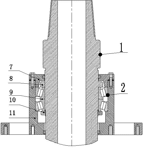
[0029] refer to figure 1 , a multi-hydraulic cylinder-driven top drive casing feeding tool, including a suspension mandrel 1, the suspension mandrel 1 is covered with a connection assembly 2, the lower end of the connection assembly 2 is fixedly connected with the hydraulic cylinder assembly 3 through bolts, and the hydraulic pressure The lower end of the cylinder assembly 3 is connected with the pin shaft of the transmission assembly 4, the lower end of the transmission assembly 4 is connected with the clamping assembly 5, and the clamping assembly 5 is fixed with an anti-collision ring 6 by external bolts;

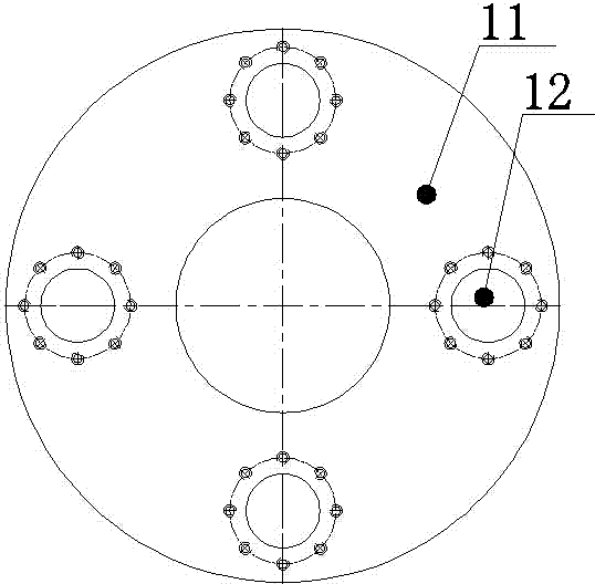
[0030] refer to figure 1 , 2 , The connection assembly 2 includes a small bearing end cover 7, a small tapered roller bearing 9, a small round nut 10, and a suspension tube 11. The diameter of the inner circular through hole of the suspension mandrel...


PUM


Abstract

A multi-hydraulic-cylinder driving type top-drive casing pipe feeding tool is characterized in that an end face of a hung cylinder is fixedly connected with a hydraulic cylinder assembly through bolts; a piston rod of the hydraulic cylinder assembly is connected with a push-pull clamping cylinder; a clip disk is arranged in the push-pull clamping cylinder; the lower end of the clip disk is connected with a clip plate, and teeth of the clip plate are spherical balls. A pair of bearings is respectively arranged between a hung mandrel and the hung cylinder and between the clip disk and the push-pull clamping cylinder, so that hydraulic cylinders can rotate relative to the hung mandrel and a clip mandrel, and the hydraulic cylinders are prevented from bearing torsion load. When the multi-hydraulic-cylinder driving type top-drive casing pipe feeding tool works, the four hydraulic cylinders can provide descending power for the clip plate simultaneously, at the same time the spherical balls contact the wall of a casing pipe, and a pipe column can be tightly clamped. The multi-hydraulic-cylinder driving type top-drive casing pipe feeding tool has the advantages of preventing the spherical balls from being meshed into the pipe wall, well solving the problems of damage to the pipe wall and abrasion of the clip plate, simplifying a complex device structure by using one single hydraulic cylinder and reducing the manufacturing cost. Furthermore, the multi-hydraulic-cylinder driving type top-drive casing pipe feeding tool can timely rotate, lift and release the pipe column and circulate pulp, the casing pipe feeding operation efficiency and the safety are improved, and the comprehensive well drilling cost is reduced.

Description

technical field [0001] The invention relates to the technical field of oil and gas well cementing equipment, in particular to a multi-hydraulic cylinder driven top drive casing running tool. Background technique [0002] The purpose of casing operation is to isolate the formation, strengthen the well wall, prevent oil and gas leakage, and establish oil and gas passages. It is an extremely important link in the process of oil and gas drilling operations. The casing running tool is the key equipment to complete the casing operation. The conventional casing running equipment mainly includes: wellhead slips for clamping casing, hydraulic casing tongs for casing twist, intermittent Tools such as open grouting device for grouting, casing elevator for lifting casing, etc. [0003] However, the above-mentioned conventional casing running equipment has the following problems: the wellhead slip tooth plate is tooth-shaped, and when the suspension casing is clamped, the slip teeth wil...

Claims


Application Information

Patent Timeline
IPC IPC(8): E21B7/20
CPCE21B7/20
Inventor 蒋发光谢帅卓昌荣刘晓宁张佳佳谭晓波张伟李贞丽张敏
Owner SOUTHWEST PETROLEUM UNIV
Learn More