Control ring for a hydrostatical device

A control ring and control piston technology, which is applied to the components of the pumping device for elastic fluids, pump control, liquid fuel engines, etc., can solve problems such as leakage, and achieve the effect of simple connection and prevention of leakage

Inactive Publication Date: 2015-07-15
MOOG INC
View PDF8 Cites 2 Cited by
  • Summary
  • Abstract
  • Description
  • Claims
  • Application Information

AI Technical Summary

Problems solved by technology

Another issue is to adequately seal the valve plate to avoid leakage in the control interface

Method used


Image

  • Control ring for a hydrostatical device
  • Control ring for a hydrostatical device
  • Control ring for a hydrostatical device

Examples


Embodiment Construction

[0027] Only two embodiments of the invention are shown and described below, simply by way of illustration of one mode of carrying out the invention. All illustrations are schematic.

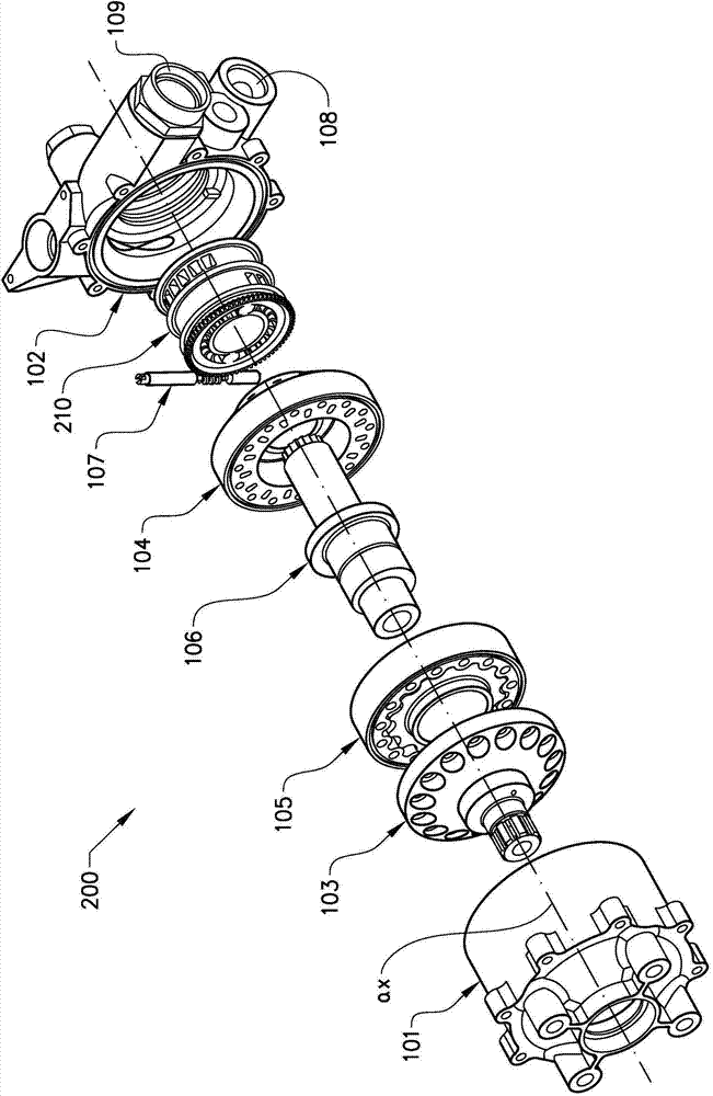
[0028] figure 1 A piston pump 200 is disclosed, in which the control loop 210 of the present invention is arranged. Piston pump 200 is disclosed as a gerotor pump. But the control ring 10, 210 of the present invention is compatible with any piston pump having a fixed pressure chamber. The piston pump 200 includes front and rear housings 101 , 102 , with front and rear plates 103 , 104 of the rotor set 105 arranged therebetween, on which the eccentric shaft 106 of the rotor set 105 and a control ring 210 are mounted. The rotor pack 105 is arranged between a front plate 103 and a rear plate 104, wherein the rear plate 104 is provided with supply ducts to connect the pressure chambers of the rotor pack with inlet 108 and outlet 109 in the rear housing.

[0029] In the illustrated embodiment, the...


PUM


Abstract

Control ring (10; 210) for controlling the flow of a pressure medium in a displacement pump (200), said control ring (10; 210) is; €¢ centred about a rotational axis (ax) €¢ extending along said rotational axis (ax), €¢ having an inner and an outer diameter (d, D) and thereby an inner and outer radial surface (11, 12; 211, 212) €¢ a first and a second axial surface (13, 14; 213, 214), wherein said first axial surface (13; 213) having an interface section (20; 220) provided with at least a first and a second opening (21, 22; 221, 222), which first and second opening (21, 22; 221, 222) are separated by a first and a second intermediate section (15, 16; 215, 216), characterised in, that said first and second opening (21, 22; 221, 222) are mouthing to a corresponding mouthing area provided at either of the inner and outer radial surface (11, 12; 211, 212).

Description

technical field [0001] The invention relates to piston pumps and in particular to a control ring for a piston pump. Background technique [0002] In document EP 2 497 950 an adjustable port plate is described. The port plate is provided with first and second orifices adapted to correspond to first and second pressure chambers of the piston pump. By turning the valve plate, the displacement of the piston pump can be controlled. [0003] A problem with the valve plate according to the prior art is that the valve plate becomes larger in diameter due to its pressure equalization area outside the control orifice. Another problem is to adequately seal the valve plate to avoid leakage in the control port. [0004] Therefore, there is a need for an improved arrangement for controlling a piston pump in which the above-mentioned disadvantages are avoided. Contents of the invention [0005] It is an object of the present invention to provide an inventive control for displacement ...

Claims


Application Information

Patent Timeline
Patent Type & Authority Applications(China)
IPC IPC(8): F04B53/00
CPCF04C14/14F04C2/102F04B49/22
Inventor C·奥登马克J·福塞尔
Owner MOOG INC
Why Eureka
Try Eureka