Fixed guide vane body inlet angle adjustable axial flow pump

A technology for fixing guide vanes and inlet angles, which is applied to components, pumps, and pump components of pumping devices used for elastic fluids, and can solve the problems of unstable operation, easy impact loss, and inability to adjust axial flow pumps , to achieve the effect of improving work stability, reducing impact loss and easy operation

Inactive Publication Date: 2015-07-15
CHINA AGRI UNIV
View PDF6 Cites 4 Cited by
  • Summary
  • Abstract
  • Description
  • Claims
  • Application Information

AI Technical Summary

Problems solved by technology

[0004] However, the guide vanes of traditional axial flow pumps are designed according to the rated working conditions and fixed on the hub of the guide vane body at a certain installation angle, which cannot be adjusted accordingly with changes in working conditions.
However, when the axial flow pump operates under non-design conditions, there is an attack angle between the placement angle of the guide vane body and the liquid flow angle at the outlet of the impeller, which is prone to impact loss
At the same time, according to the design experience, the inlet side of the guide vane is generally parallel to the outlet side of the impeller, and the distance between them should be (0.05-0.1) D. If the distance is not designed properly, it will easily lead to unstable operation of the axial flow pump, thereby affecting its efficiency.

Method used


Image

  • Fixed guide vane body inlet angle adjustable axial flow pump
  • Fixed guide vane body inlet angle adjustable axial flow pump
  • Fixed guide vane body inlet angle adjustable axial flow pump

Examples


Embodiment Construction

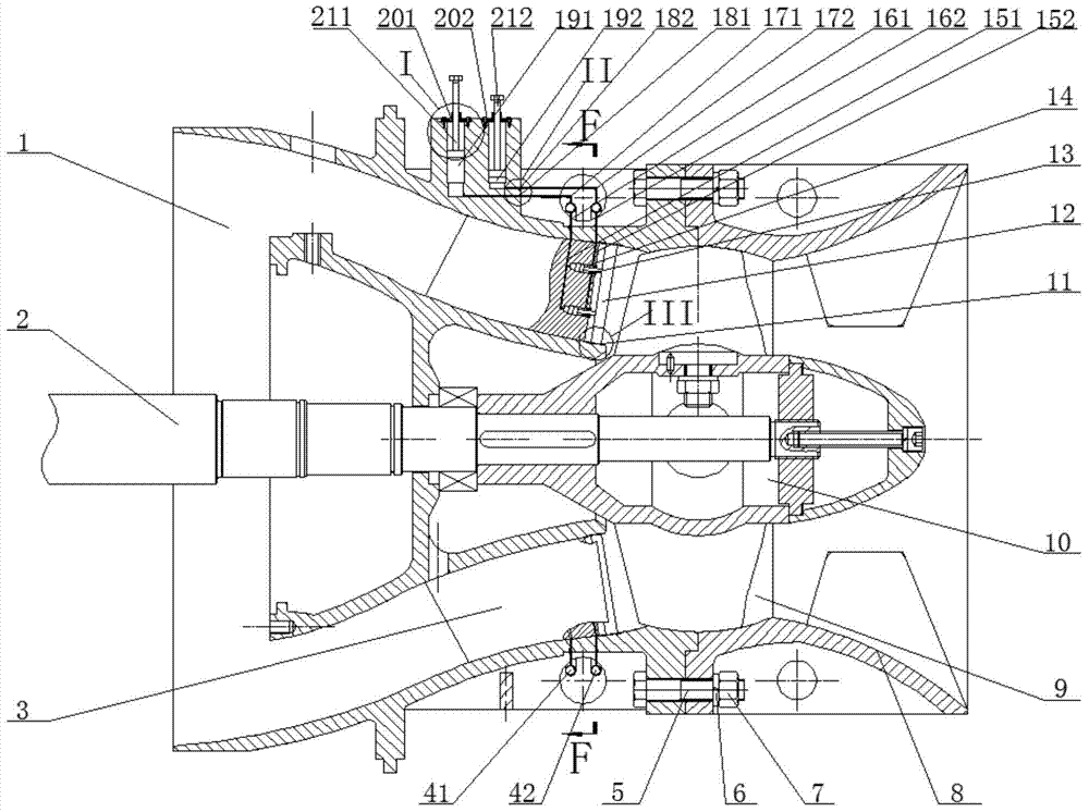
[0073] The specific implementation manner of the present invention will be described in detail below in conjunction with the accompanying drawings and embodiments. The following examples are used to illustrate the present invention, but are not intended to limit the scope of the present invention.

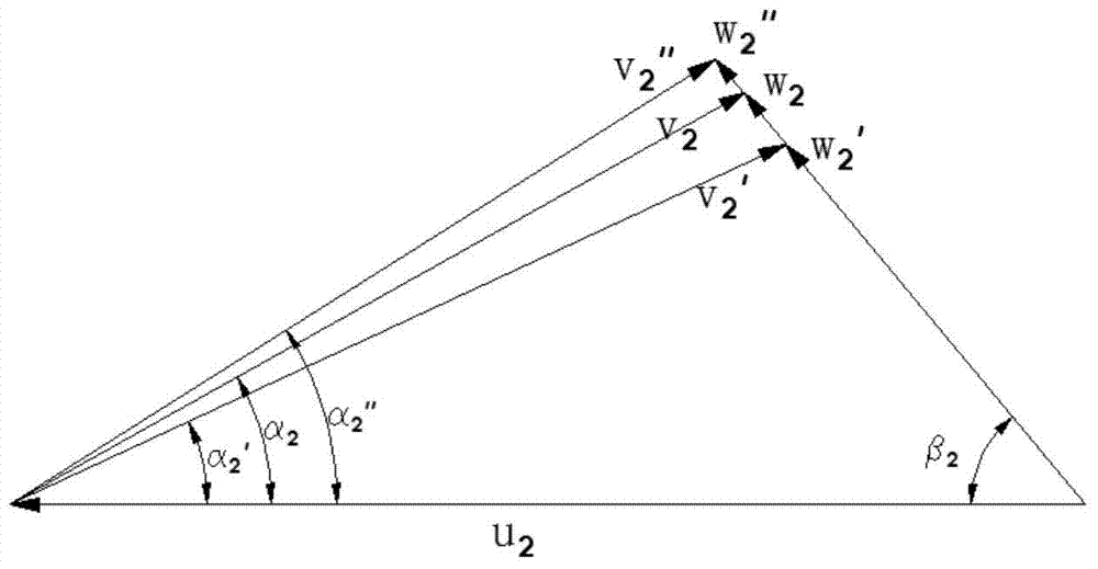
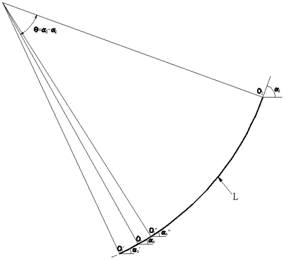
[0074] figure 1 It is the overall cross-sectional view of the axial flow pump with adjustable inlet angle of the fixed guide vane body of the present invention; Figure 1a is the schematic diagram of the impeller outlet velocity triangle; Figure 1b is the bone line diagram of the guide vane airfoil; Figure 1c , Figure 1d and Figure 1e respectively Figure 1b Middle O 1 'Point, O 1 dot and o 1 Schematic diagram of the guide vane inlet velocity triangle of the airfoil bone line at "point; figure 2 for figure 1 Partial enlarged view of part I in middle; image 3 for figure 1 Partial enlarged view of part II in middle; Figure 4 for figure 1 Partial enlarged view of ...


PUM


Abstract

The invention relates to the technical field of water pumps, in particular to a fixed guide vane body inlet angle adjustable axial flow pump which comprises an impeller chamber (9), a water inlet horn mouth (8), an impeller body (10), a guide vane body (1) and a pump shaft (2). The guide vane body (1) comprises a plurality of guide vanes (3) and a dispersing pipe. The axial flow pump further comprises an adjusting system which comprises a control unit, a middle unit and an executing unit. According to different working conditions, a proper guide vane inlet angle is adjusted, so that the guide vane inlet angle is matched with an impeller flow-out angle, the circular rector of the fixed guide vane body is changed, accordingly, stress is improved, then, hydraulic loss such as impact and streaming around is lowered, energy loss is lowered, the operation stability of the pump is improved, and finally the purpose of axial flow pump performance improving is achieved.

Description

technical field [0001] The invention relates to the technical field of water pumps, in particular to an axial flow pump with an adjustable inlet angle of a fixed vane body. Background technique [0002] Axial flow pump is a widely used hydraulic mechanical device. It has the characteristics of large flow and low head, and is widely used in large-scale farmland drainage and irrigation and water transfer projects. The extensive use of axial flow pumps will inevitably increase the demand for energy. Therefore, reducing the hydraulic loss of axial flow pumps and improving their efficiency is of great significance to energy conservation and emission reduction. [0003] In order to improve the efficiency of the axial flow pump, methods such as optimizing the structural design of the impeller and the flow channel can be used, but this method generally consumes relatively high costs. Considering that the absolute velocity of the impeller outlet of the axial flow pump has a certain ...

Claims


Application Information

Patent Timeline
Patent Type & Authority Applications(China)
IPC IPC(8): F04D29/56
Inventor 唐学林邹明德
Owner CHINA AGRI UNIV
Why Eureka
Try Eureka