
Directly under backlight device

A backlight and direct-type technology, which is applied in the field of direct-type backlight devices, can solve the problems of insufficient brightness, high cost, uneven tube brightness, etc., and achieve the effect of suppressing uneven tube brightness

Inactive Publication Date: 2015-07-15
TORAY IND INC
View PDF9 Cites 2 Cited by
  • Summary
  • Abstract
  • Description
  • Claims
  • Application Information

AI Technical Summary

Problems solved by technology

[0010] However, direct-type backlights used in flat-panel TVs, direct-type backlights that reduce the number of fluorescent tubes installed in order to reduce power consumption in view of environmental protection, and point light sources that contain low levels of heavy metals such as mercury have attracted attention in recent years. That is, the direct-lit backlight device of LED is likely to produce uneven brightness and insufficient brightness.
Therefore, it is necessary to use a plurality of the above-mentioned optical members, and it may be difficult to reduce the thickness, resulting in an increase in cost, and furthermore, the power consumption used in the manufacture of optical members may increase, which may increase the environmental load on the contrary.

Method used


Image

  • Directly under backlight device
  • Directly under backlight device
  • Directly under backlight device

Examples


Embodiment 1

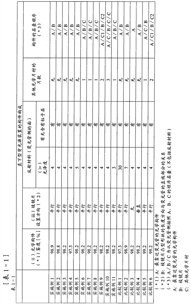
[0138] In the configurations A to D below, the evaluation was performed using the above-mentioned devices 1, 2 and 3.

[0139] A: Clarex (registered trademark) DR-III C-A DR-80C (manufactured by Nitto Plastic Industry Co., Ltd.)

[0140] B: vikuiti BEFIII 90 / 50T (manufactured by 3M Corporation, convex shape: triangle with vertex angles at right angles, pitch of convex shapes: 50 μm) (set in parallel direction)

[0141] C: None

[0142] D: Lumirror (registered trademark) E6QD (manufactured by Toray Co., Ltd., thickness 188 μm)

[0143] Stacking order: A / B.

Embodiment 2

[0145] In the configurations A to D below, the evaluation was performed using the above-mentioned devices 1, 2 and 3.

[0146] A: Sumipex E (registered trademark) RM804S (manufactured by Sumitomo Chemical Co., Ltd.)

[0147] B: vikuiti BEFIII 90 / 50T (manufactured by 3M Corporation, convex shape: triangle with vertex angles at right angles, pitch of convex shapes: 50 μm) (set in parallel direction)

[0148] C: None

[0149] D: Lumirror (registered trademark) E6QD (manufactured by Toray Co., Ltd., thickness 188 μm)

[0150] Stacking order: A / B.

Embodiment 3

[0152] First, a 32-inch LCD TV (manufactured by Hitachi, Ltd., Wooo (registered trademark) UT32-Hv700B), which has a plurality of convex shapes extending in one direction on the surface opposite to the fluorescent tube side, was obtained. A resin plate with a thickness of 2 mm and a convex shape whose longitudinal direction is parallel to the linear direction of the fluorescent tube. For this resin plate, the haze value based on JIS K7136 (2000) when light is incident from the fluorescent tube side at the time of mounting before disassembly is 98.3%, and the incident surface is directly rotated 90° from this state, and measured in the same manner, As a result, the haze value was 98.1%.

[0153] Taking the average value, the haze value of this resin plate was 98.2%.

[0154] Next, after cutting this resin plate into a size that can be installed in the above-mentioned devices 1 to 5 (hereinafter abbreviated as a concave-convex pattern resin plate), evaluation was performed usin...


PUM


Abstract

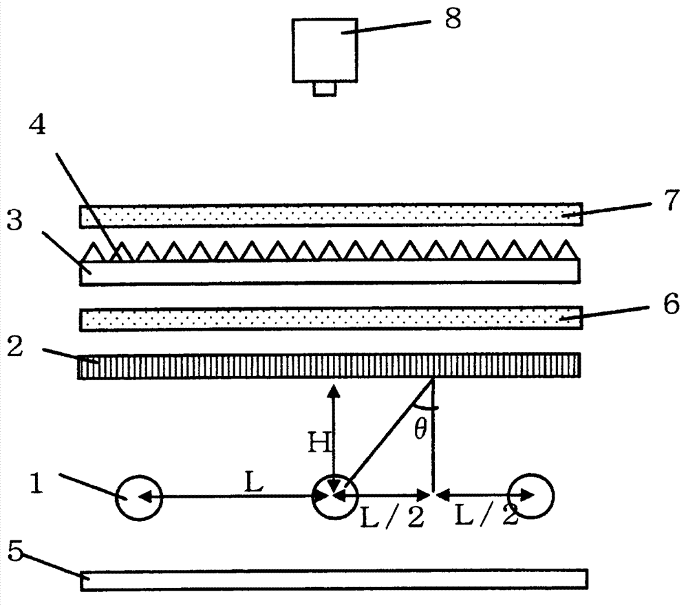
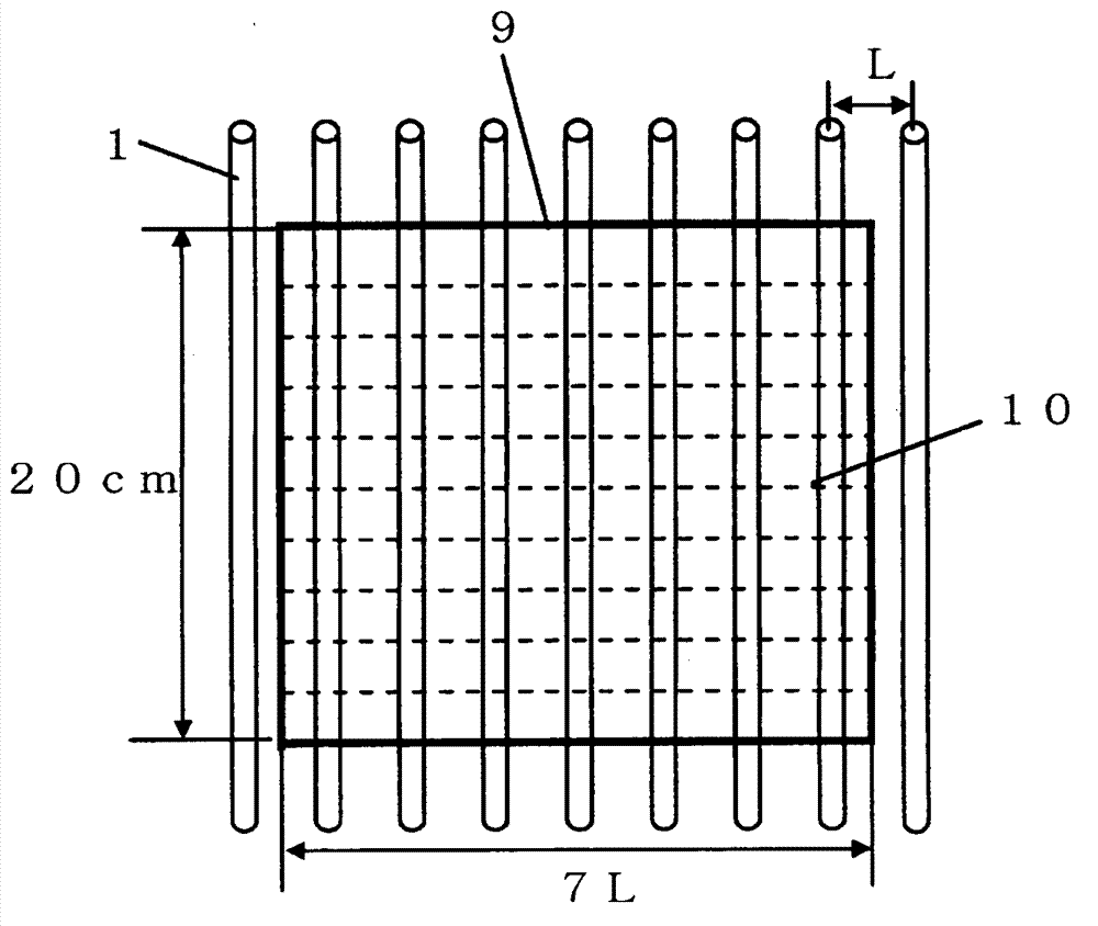
Provided is a directly under backlight device for a display unit of high brightness by minimizing uneven brightness of tubes efficiently without using an optical member subjected to special processing.  The directly under backlight device comprises a reflective material, a plurality of linear light sources, and a group of optical members that are arranged in this order, and satisfies the following conditions (i)-(v).  (i) The plurality of linear light sources are arranged with the longitudinal directions thereof in parallel. (ii) The optical member, closest to the linear light sources, in the group of optical members has a haze value of 99.0% or less based on the JIS K 7136 (2000) and measured by making light enter from the surface on the linear light source side. (iii) There is a prism sheet in the group of optical members, a plurality of protrusions extending in one direction are formed on the surface of the prism sheet which is on the reverse side of the linear light source, the plurality of protrusions are parallel in the longitudinal direction, and the longitudinal direction of the plurality of protrusions is parallel with the longitudinal direction of the plurality of linear light sources. (iv) The reflective material has a 60° glossiness of 5 or less measured based on the JIS K 7105 (1981) for the surface on the linear light source side. (v) Assuming the distance between the centers of adjoining linear light sources in the plurality of linear light sources is L, and the distance from the center of the linear light source to an optical member closest to the linear light source is H, ? satisfying the following expression (1) falls in a range of 45°=?=70°. ?=tan-1((L / 2) / H) ... expression (1).

Description

[0001] This application is a divisional application of Chinese patent application 200980127476.9 (PCT application number PCTJP2009 / 065384) with a filing date of September 3, 2009 and an invention title of "Direct Type Backlight Device". technical field [0002] The present invention relates to various display devices, especially a direct-type backlight source device of a liquid crystal display device. Background technique [0003] Liquid crystal display devices are used in various applications such as notebook computers and mobile phones, televisions, monitors, and car navigation systems. A liquid crystal display device incorporates a backlight unit as a light source, and has a structure in which light emitted from the backlight unit is passed into a liquid crystal element and controlled to perform display. The characteristic required for this backlight device is not only to be a light source that simply emits light, but also to make the entire screen brightly and uniformly ...

Claims


Application Information

Patent Timeline
Patent Type & Authority Applications(China)
IPC IPC(8): F21S2/00F21Y103/00
CPCG02F1/133606G02F1/133604
Inventor 河田融司佐藤义和渡边修坂口善彦
Owner TORAY IND INC
Learn More