
A high-energy-saving and environment-friendly liquid burner

An energy saving, environmental protection, burner technology, applied in liquid fuel burners, burners, burners, etc., can solve problems such as flame instability, and achieve the effect of uniform and stable wind force, convenient fixation, and uniform distribution.

Active Publication Date: 2017-05-03
陈民
View PDF11 Cites 0 Cited by
  • Summary
  • Abstract
  • Description
  • Claims
  • Application Information

AI Technical Summary

Problems solved by technology

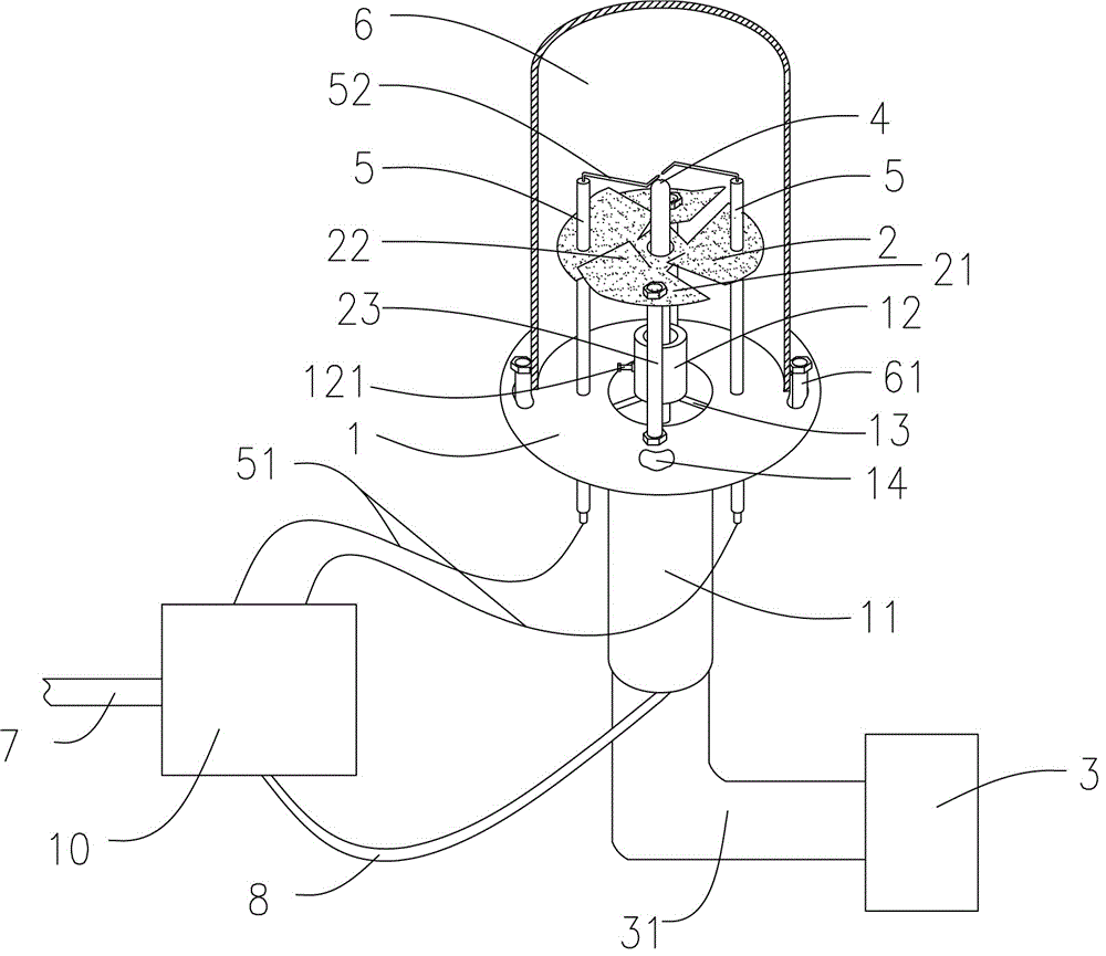
[0003] The technical problem to be solved by the present invention is that when the current combustion stove uses liquid fuel, the liquid fuel flows into the ignition device by its own gravity, and is manually ignited, and the flame is unstable; in order to solve the above problems, the present invention provides a high energy-saving The environmentally friendly liquid burner includes an ignition part and a control pressurization part. The ignition part includes an ignition needle and a fuel injection nozzle; The upper end of the fuel injection nozzle is located below the needle of the ignition needle; the liquid fuel enters the control pressurization part through the oil inlet pipe, and is connected with the lower end of the fuel injection nozzle through the oil outlet pipe; The jet is ignited by the ignition pin

Method used


Image

  • A high-energy-saving and environment-friendly liquid burner
  • A high-energy-saving and environment-friendly liquid burner
  • A high-energy-saving and environment-friendly liquid burner

Examples


Embodiment Construction

[0018] The technical solution of the present invention will be further described below in conjunction with the accompanying drawings.

[0019] Such as figure 1 As shown, a high-energy-saving and environment-friendly liquid burner according to an embodiment of the present invention includes an ignition part and a control pressurization part. The ignition part includes an ignition needle 5 and a fuel injection nozzle 4. There are two ignition needles 5. There is an ignition needle 52, and the two needles are arranged opposite to each other. The lower end of the ignition needle 5 is connected to the control pressurization part 10 through the high-voltage ignition wire 51, and the upper end of the fuel injection nozzle 4 is located below the ignition needle 5. The pressure part 10 is connected to the lower end of the fuel injection nozzle 4 through the fuel outlet pipe 8. After the needle of the ignition needle is ignited by a high-voltage pulse, the liquid fuel is ejected from th...


PUM


Abstract

The invention provides a novel high-energy-saving environment-friendly liquid combustor. The novel combustor comprises an igniting part and a control pressuring part, wherein the igniting part comprises an igniting needle and an oil injection nozzle; an igniting needle head is arranged at the upper end of the igniting needle; the lower end of the igniting needle is connected with the control pressurizing part through a high-voltage ignition wire; the upper end of the oil injection nozzle is positioned below the igniting needle head; liquid fuel enters the control pressurizing part through an oil inlet pipe; then the liquid fuel is connected with the lower end of oil injection nozzle through an oil outlet pipe; the igniting needle is ignited by high voltage pulse; the liquid fuel is erupted through the oil injection nozzle to be ignited by the igniting needle. According to the novel high-energy-saving environment-friendly liquid combustor, the liquid fuel is pressurized and controlled through the control pressuring part; the flame size can be controlled by controlling the flow of the liquid fuel; the pulse ignition of the igniting needle can be realized through the control pressurizing part, so that the novel combustor is quite efficient and convenient.

Description

technical field [0001] The invention relates to the technical field of stoves and heating boilers, in particular to a high energy-saving and environment-friendly liquid burner using liquid as fuel. Background technique [0002] The current stoves generally use natural gas as the raw material for combustion. Since petroleum is a non-renewable resource, natural gas resources are in short supply, and the price continues to rise, which greatly increases the cost of use. In order to save resources, liquid fuels have gradually entered people's field of vision, but how to use liquid fuels conveniently and efficiently still needs further development and research. In the prior art, a ball valve is generally used to control the entry of liquid fuel into the ignition device. The liquid fuel generally flows into the ignition device by its own gravity, and the ignition is controlled by a lighter. This will easily cause problems such as uneven flame size and easy leakage of liquid fuel. ...

Claims


Application Information

Patent Timeline
Patent Type & Authority Patents(China)
IPC IPC(8): F23D11/24F23D11/36
CPCF23D11/24F23D11/36F23D11/42F23D2202/00F23D2207/00F23D2208/00
Inventor 陈民
Owner 陈民
Learn More