
A device and method for measuring coaxiality

A coaxiality and detected technology, applied in the field of coaxiality measuring devices

Active Publication Date: 2017-08-25
XIAN NORTH ELECTRO OPTIC TECH DEFENSE
View PDF6 Cites 0 Cited by
  • Summary
  • Abstract
  • Description
  • Claims
  • Application Information

AI Technical Summary

Problems solved by technology

[0003] At present, in terms of coaxiality measurement, the method of visual reading measurement of dial indicator is almost used. This method has certain limitations, such as it must be contact measurement, reading measurement based on human eyes, etc.

Method used


Image

  • A device and method for measuring coaxiality
  • A device and method for measuring coaxiality

Examples


Embodiment 1

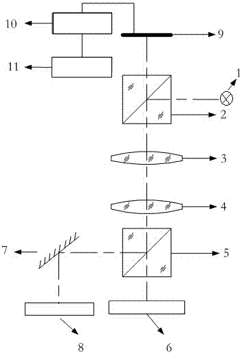
[0028] Such as figure 1 As shown, a device for measuring coaxiality includes a light source 1, and a beam-splitting prism 1 placed on the exit surface of the light source 1, and a lens 3, a beam-splitting prism 2, and a beam-splitting prism are sequentially arranged below the beam-splitting prism 1. A detected axis 6 is arranged below the second 5, a plane reflector 7 placed at a 45° angle is arranged on the left side of the dichroic prism two 5, and a detected axis two 8 is arranged below the plane reflector 7; above the dichroic prism one 2, there is A CCD detector 9 , the CCD detector 9 is electrically connected to a processor 10 , and the processor 10 is electrically connected to a computer 11 . The invention adopts a CCD detector with high quantum detection efficiency, high spatial resolution, high density resolution, high dynamic range, and can obtain the best image, the image quality is reliable and consistent for a long time, and the use cost is greatly reduced.

Embodiment 2

[0030] On the basis of embodiment 1,

[0031] The light source 1 of the present invention is a semiconductor laser point light source, and the semiconductor laser point light source has the characteristics of clarity, good consistency, and long service life; the lens one 3 and lens two 4 are convex lenses; the beam splitting prism one 2 and the beam splitting Prism 2 5 is a polarizing beam splitting prism with high extinction ratio.

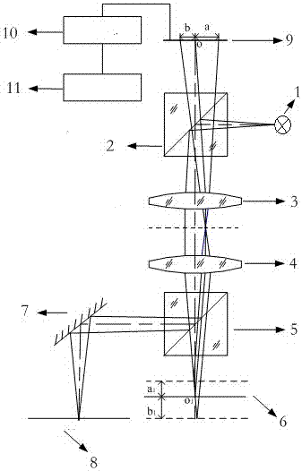
[0032] Such as figure 2 As shown, a method for measuring coaxiality comprises the following steps:

[0033] 1) Build the optical path, set the light source at the focal point of lens 1, so that the light beam emitted by the light source passes through the beam splitter prism 1 and lens 1 to form a parallel beam; when the lens 1 and lens 2 are set, the focus positions coincide; the parallel beams converge after passing through the lens 2 , and then transmitted through the second beam splitter prism to reach the axis one, the first axis is set a...


PUM


Abstract

The invention discloses a device and a method for measuring coaxiality. The device includes a light source and a beam splitting prism one placed on the light source exit surface. A lens one, a lens two and a beam splitting prism two are sequentially arranged under the beam splitting prism one. A detected axis 1 is arranged below the beam-splitting prism 2, and a plane mirror placed at a 45° angle is arranged on the left side of the beam-splitting prism 2, and a detected axis 2 is arranged below the plane mirror; a CCD detector is arranged above the beam-splitting prism 1, so The CCD detector is electrically connected to the processor, and the processor is electrically connected to the computer. The method includes: 1) building an optical path; 2) calibrating the CCD detector; 3) adjusting the optical path; 4) imaging the reflected light trajectory of the detected axis 1 and axis 2 on the CCD detector and outputting it to the computer through the processor; 5) computer Carry out trajectory fitting and calculate the concentricity value. Its principle is simple, strong implementability, good stability, with the advantages of automation and intelligence, and can realize on-line measurement of coaxiality.

Description

technical field [0001] The invention relates to a coaxiality measuring device in the technical field of optical detection, in particular to a device and method for measuring coaxiality during the assembly process of a shaft coupling. Background technique [0002] In mass industrial production, the highly automated production process and the increasing product quality require more effective, accurate and high-speed detection and identification methods. Optical detection technology can ensure the reliability in the industrial field environment, improve the degree of production automation, and greatly improve production efficiency. Therefore, in the modern automated production process, optical detection is widely used in product identification, quality control, measurement inspection, automation equipment and other fields. [0003] At present, in terms of coaxiality measurement, almost all of them use the method of visual reading measurement of dial indicator. This method has ...

Claims


Application Information

Patent Timeline
Patent Type & Authority Patents(China)
IPC IPC(8): G01B11/27
Inventor 张晓李时威胡振民朱宏斌王静
Owner XIAN NORTH ELECTRO OPTIC TECH DEFENSE
Learn More