A method for separation and detection of nanoparticles
A nanoparticle and detection method technology, applied in the direction of particle suspension analysis, measurement device, test sample preparation, etc., can solve the problems of unclear particle size distribution range, etc., and achieve rapid separation, high resolution, and wide separation range Effect
- Summary
- Abstract
- Description
- Claims
- Application Information
AI Technical Summary
Problems solved by technology
Method used
Image
Examples
Embodiment 1
[0057] Embodiment 1: Separation and detection of nano-silver particles
[0058] a. Pretreatment of the aqueous solution containing nano-silver particles
[0059] The pretreatment of the aqueous solution containing nano-silver particles includes two steps of suction filtration and concentration. The water sample was filtered through a 0.45 μm cellulose acetate membrane, and the filtrate was concentrated using a stirring ultrafiltration cup. The ultrafiltration membrane was selected from Millipore 10KD cellulose acetate membrane, and the concentration factor was set to 10 times.
[0060] b, using asymmetric flow field flow separation technology to separate the product obtained in step a
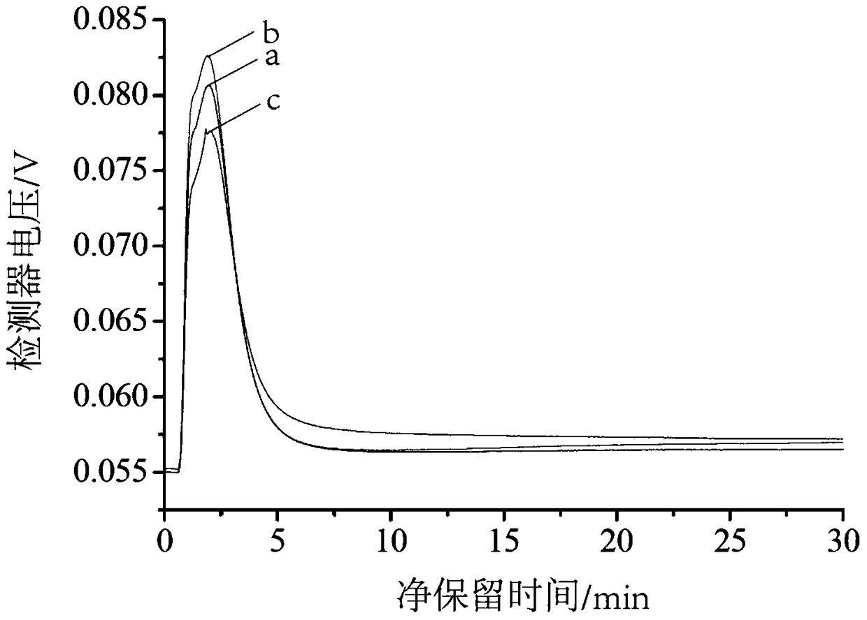
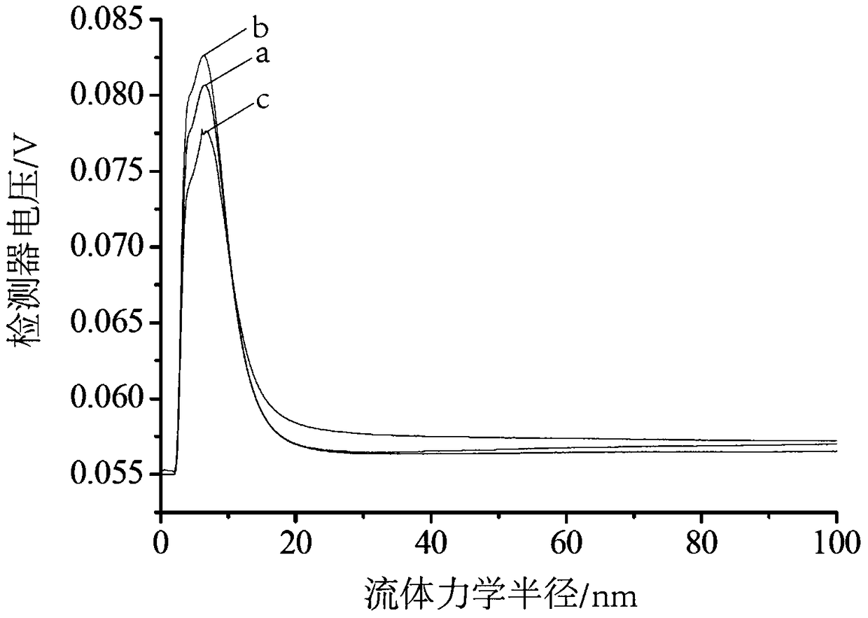
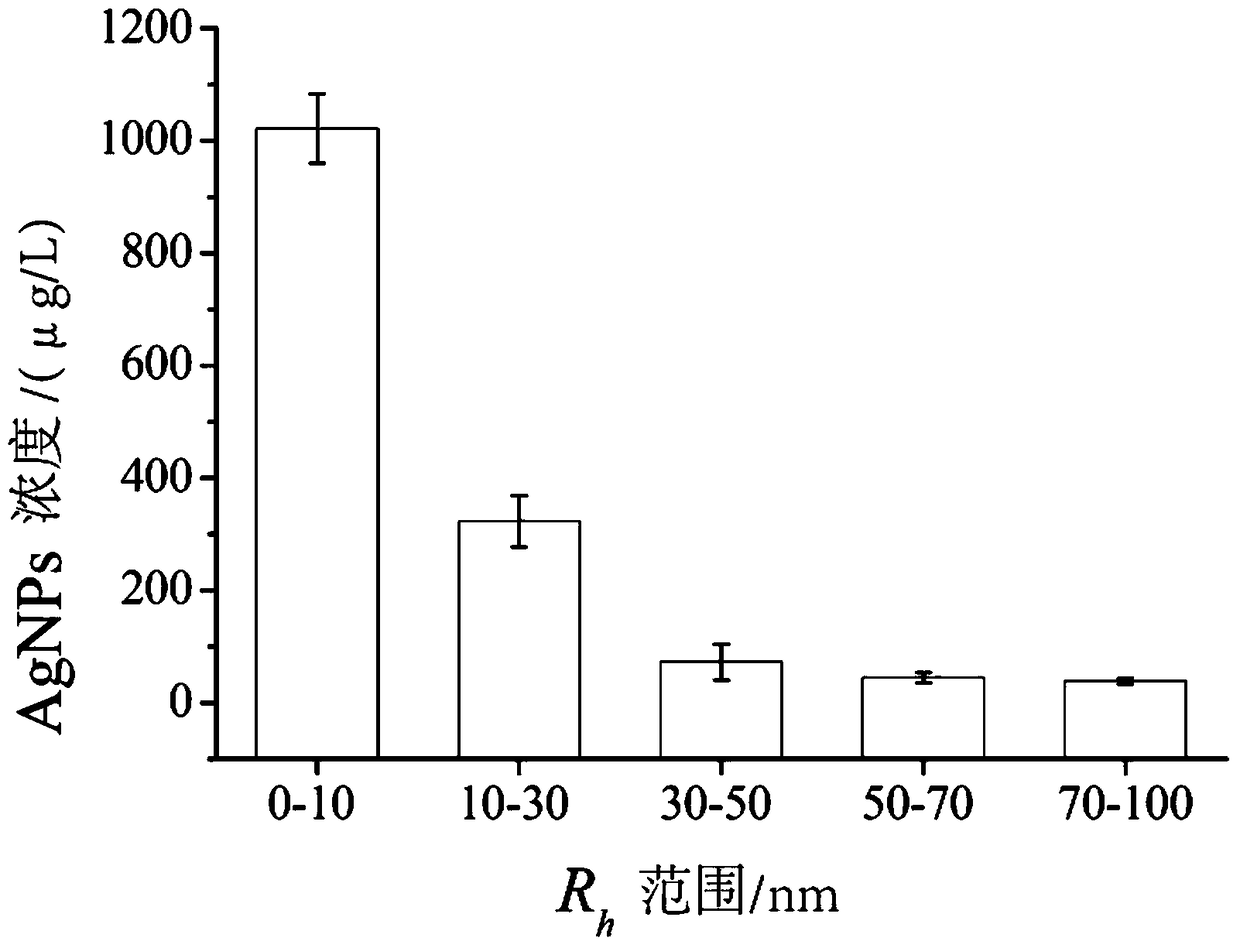
[0061] Obtain the retention time and response signal spectrum of a, b, c three parallel experiments by online UV-vis (such as figure 1 shown), use the ISIS software to set the abscissa t R Convert to R h , get the abscissa as R h , the ordinate is the spectrum of the UV-vis response signal...
Embodiment 2
[0067] Example 2: Nano C 60 separation detection
[0068] a. For nano-C 60 aqueous solution for pretreatment
[0069] Containing nano-C 60 The pretreatment of the aqueous solution includes two steps of suction filtration and concentration. The water sample was filtered through a 0.45 μm cellulose acetate membrane, and the filtrate was concentrated using a stirring ultrafiltration cup. The ultrafiltration membrane was selected from Millipore 10KD cellulose acetate membrane, and the concentration factor was set to 10 times.
[0070] b, using asymmetric flow field flow separation technology to separate the product obtained in step a
[0071] Nano C obtained by online UV-vis 60 Retention time and response signal spectrum of three parallel experiments a, b, c, such as Figure 5 shown.
[0072] Use ISIS software to set the abscissa t R Convert to R h , get the abscissa as R h , the ordinate is the spectrum of the UV-vis response signal, such as Figure 6 shown. The resul...
Embodiment 3
[0079] Embodiment 3: Nano α-Fe 2 o 3 separation detection
[0080] a. For nano α-Fe 2 o 3 aqueous solution for pretreatment
[0081] Containing nano-α-Fe 2 o 3 The pretreatment of the aqueous solution includes two steps of suction filtration and concentration. The water sample was filtered through a 0.45 μm cellulose acetate membrane, and the filtrate was concentrated using a stirring ultrafiltration cup. The ultrafiltration membrane was selected from Millipore 10KD cellulose acetate membrane, and the concentration factor was set to 10 times.
[0082] b, using asymmetric flow field flow separation technology to separate the product obtained in step a
[0083] Nano-sized α-Fe obtained by on-line UV-vis connected with an asymmetric flow long-flow separation system 2 o 3 Retention time and response signal spectrum of three parallel experiments a, b, c (such as Figure 10 shown), use the ISIS software to set the abscissa t R Convert to R h , get the abscissa as R h , ...
PUM
| Property | Measurement | Unit |
|---|---|---|
| electrical resistivity | aaaaa | aaaaa |
| radius | aaaaa | aaaaa |
| radius | aaaaa | aaaaa |
Abstract
Description
Claims
Application Information
 - R&D
- Intellectual Property
- Life Sciences
- Materials
- Tech Scout
- Unparalleled Data Quality
- Higher Quality Content
- 60% Fewer Hallucinations
Browse by: Latest US Patents, China's latest patents, Technical Efficacy Thesaurus, Application Domain, Technology Topic, Popular Technical Reports.
© 2025 PatSnap. All rights reserved.Legal|Privacy policy|Modern Slavery Act Transparency Statement|Sitemap|About US| Contact US: help@patsnap.com


