Photomask device for optical alignment and application equipment

A technology of photo-alignment and photomask, which is applied in microlithography exposure equipment, photomechanical equipment, photo-plate-making process exposure devices, etc. It can solve the problems that hinder the display quality of products, and achieve the effect of smooth exposure

Active Publication Date: 2015-07-15
TCL CHINA STAR OPTOELECTRONICS TECH CO LTD
View PDF5 Cites 16 Cited by
  • Summary
  • Abstract
  • Description
  • Claims
  • Application Information

AI Technical Summary

Problems solved by technology

[0006] However, in the prior art, the openings in the overlapping regions of multiple photomasks used for photo-alignment change linearly, that is, the corresponding exposure amount also changes linearly, which makes the subsequent production of display panels have band-shaped mura defects, which hinders the display of products. quality

Method used


Image

  • Photomask device for optical alignment and application equipment
  • Photomask device for optical alignment and application equipment
  • Photomask device for optical alignment and application equipment

Examples


Embodiment Construction

[0048] The present invention will be described in detail below in conjunction with the accompanying drawings and embodiments.

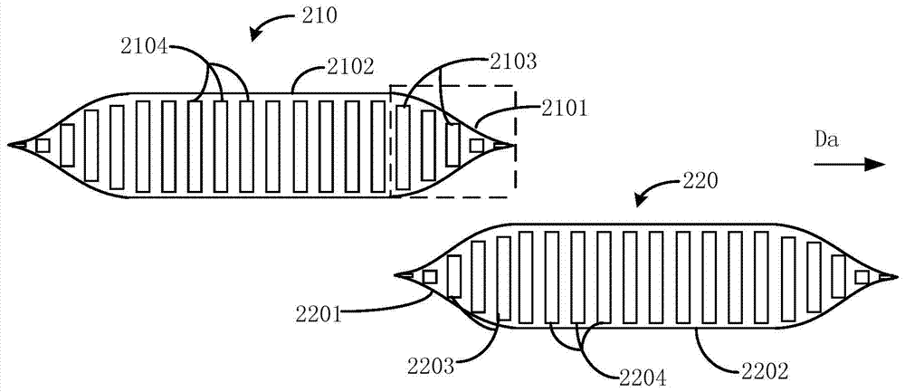
[0049] see Figure 2a and Figure 2b , Figure 2a It is a structural schematic diagram of the first embodiment of the photomask device for photo-alignment provided by the present invention; Figure 2b yes Figure 2a Schematic diagram of the structure of the variation trend of the opening height of the overlapping area of ​​the two masks in .

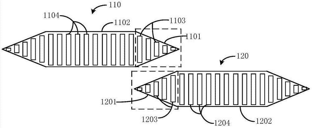
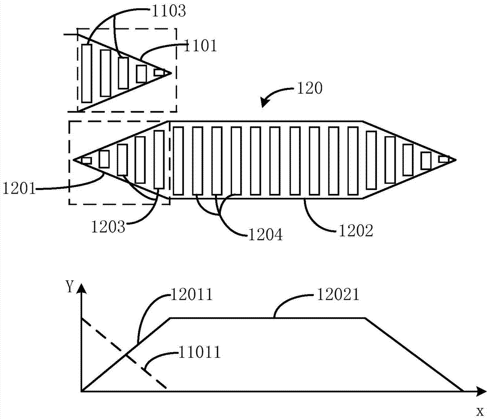
[0050] The photomask device 20 includes:

[0051] a first photomask 210 and a second photomask 220;

[0052] The first mask 210 includes a first overlapping area 2101 and a first non-overlapping area 2102;

[0053] The second mask 220 includes a second overlapping area 2201 and a second non-overlapping area 2202;

[0054] The first overlapping region 2101 and the second overlapping region 2201 overlap each other;

[0055] The first overlapping region 2101 includes a plurality of transmissive openings 210...


PUM


Abstract

The invention discloses a photomask device for optical alignment and application equipment. The photomask device comprises a first photomask and a second photomask which are partially overlapped, so that the first photomask and the second photomask respectively comprise a first overlapping region, a first non-overlapping region, a second overlapping region and a second non-overlapping region; meanwhile, the first overlapping region, the first non-overlapping region, the second overlapping region and the second non-overlapping region respectively comprise a plurality of open parts; the heights of the open parts of the first overlapping region and the heights of the open parts of the second overlapping region are smoothly changed according to the square of a trigonometric function, and the heights of the open parts after the overlapping regions are overlapped at the same position are enabled to be identical with those of the open parts of the first non-overlapping region or the second non-overlapping region. Compared with the prior art, the photomask device and the application equipment disclosed by the invention have the advantages that the defects of a strip-shaped mura in a subsequent process can be eliminated, and the display quality of products is improved.

Description

technical field [0001] The invention relates to the technical field of liquid crystal displays, in particular to a photomask device and application equipment for light alignment. Background technique [0002] The liquid crystal display applies an electric field to the field generating electrodes of the upper and lower display panels, so that the liquid crystal in the liquid crystal layer is deflected under the action of the electric field, so the display image can be realized by controlling the polarized light incident on the liquid crystal layer. Currently, vertical alignment (VA, vertical alignment) mode liquid crystal displays have been extensively researched and applied due to their high contrast ratio and wide standard viewing angle. [0003] In the manufacturing process of liquid crystal displays, two methods, rubbing alignment and photo-alignment, are often used. Among them, the rubbing alignment method will generate static electricity and particle pollution, while t...

Claims


Application Information

Patent Timeline
Patent Type & Authority Applications(China)
IPC IPC(8): G02F1/1337G03F7/20
CPCG02F1/1303G02F1/133788G03F7/2045G03F7/2004
Inventor 韩丙施明宏李蒙
Owner TCL CHINA STAR OPTOELECTRONICS TECH CO LTD
Why Eureka
Try Eureka