Light vibration touch apparatus

A touch device and vibration signal technology, applied in the direction of instruments, electrical digital data processing, input/output process of data processing, etc., can solve the problem that the total reflection inside the light guide plate cannot be destroyed, the total reflection inside the light cannot be destroyed, and the control cannot be obtained. Signal and other issues

Active Publication Date: 2015-07-15
INFILM OPTOELECTRONICS
View PDF12 Cites 4 Cited by
  • Summary
  • Abstract
  • Description
  • Claims
  • Application Information

AI Technical Summary

Problems solved by technology

However, if the light does not enter the light guide plate at a specific angle, it cannot undergo total internal reflection inside the light guide plate.
It is very difficult to finely adjust the incident angle of light and requires a matching light guide element to increase the thickness or area of ​​the touch device
In addition, if the area of ​​the contact point is very narrow, such as the tip of a toothpick, it will not be able to destroy the total internal reflection of the light propagating in the light guide plate, and it will not be possible to obtain a relative control signal

Method used


Image

  • Light vibration touch apparatus
  • Light vibration touch apparatus
  • Light vibration touch apparatus

Examples


Embodiment Construction

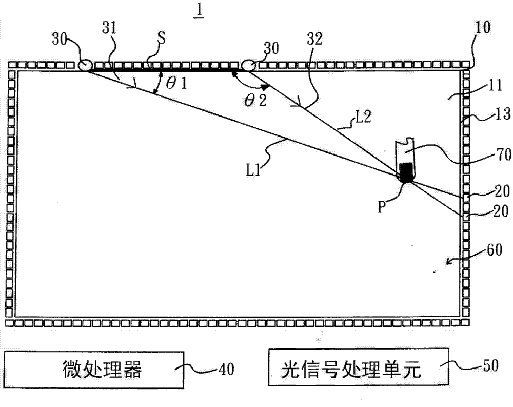
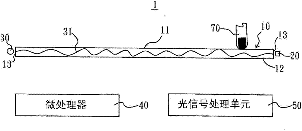
[0023] Such as figure 1 , figure 2 As shown, the optical vibration touch device 1 of the first embodiment of the present invention includes a light guide plate 10, a plurality of photosensitive units 20, at least two optical signal emitting units 30, a microprocessor 40 and an optical signal processing unit 50 composed of.

[0024] The light guide plate 10 is rectangular and has an upper end surface 11 , a lower end surface 12 and a side end surface 13 . The peripheral edge of the side of the light guide plate 10 forms a side end surface 13 . The light guide plate 10 is a bendable or non-bendable plate made of a light-guiding material, such as an acrylic plate, a resin plate, or a glass plate.

[0025] The photosensitive unit 20 can be a photodiode or any photosensitive element. The photosensitive unit 20 is in contact with or adjacent to the side end surface 13 of the light guide plate 10 for sensing the light 31 emitted by the light signal emitting unit 30 into the ligh...


PUM


Abstract

A light vibration touch apparatus comprises a guide light plate, at least a light sensitive unit, at least an optical signal emitting unit, a microprocessor, and an optical signal processor; the optical signal emitting unit emits light signal to propagate in the guide light plate; the stability of the signal influenced with vibration caused by the guide light plate being touched is utilized; the optical signal processor outputs vibration signals corresponding to a touch point; the microprocessor detects the vibration signals sequentially output by the optical signal processor in a period to obtain position information of the touch point in accordance with timings of at least two of the vibration signals appearing in the period and output a corresponding touch signal.

Description

technical field [0001] The present invention relates to a touch device, in particular to a touch device that detects the touched position of light carrying a signal when propagating in a light guide plate, and generates a corresponding control signal. Background technique [0002] There are many touch devices combined with a light guide plate. For example, US Patent No. 7,432,893 discloses an input device based on Frustrated Total Internal Reflection (FTIR), which guides light from at least two light sources at different positions into the guide. In the light plate, and make the light propagate in the light guide plate with complete internal reflection, wherein the light emitted by each light source is evenly distributed in the entire light guide plate, and a light sensor array is set on the periphery of the light guide plate to detect Light produced by a light source. When an object touches the surface of the light guide plate, it will destroy the total reflection of the l...

Claims


Application Information

Patent Timeline
Patent Type & Authority Applications(China)
IPC IPC(8): G06F3/042
CPCG06F3/0423G06F3/0428
Inventor 林志雄
Owner INFILM OPTOELECTRONICS
Why Eureka
Try Eureka