
Optical gas chamber and method for calculating total optical distance by gas chamber

An air chamber and optical technology, applied in the field of gas composition measurement by light analyzers, can solve the problems of large volume, large air chamber size, accuracy problems, etc., and achieve the effect of extending the optical path, increasing the number of reflections, and avoiding interference.

Inactive Publication Date: 2014-11-19
DONGGUAN INST OF OPTO ELECTRONICS PEKING UNIV
View PDF5 Cites 5 Cited by
  • Summary
  • Abstract
  • Description
  • Claims
  • Application Information

AI Technical Summary

Problems solved by technology

Therefore, a high-precision detection instrument means that the size of the gas chamber is larger and the volume is larger, which also means that such a gas chamber design cannot be made small and portable.
Patent No. 200820123271.6 discloses a multi-reflection gas chamber, which utilizes the principle of multiple reflections to measure in a narrow space. In the middle, the optical path generally overlaps multiple times at the waist of the pool, and the overlap in this part will lead to measurement accuracy problems

Method used


Image

  • Optical gas chamber and method for calculating total optical distance by gas chamber
  • Optical gas chamber and method for calculating total optical distance by gas chamber
  • Optical gas chamber and method for calculating total optical distance by gas chamber

Examples


Embodiment Construction

[0018] The present invention will be further described below in conjunction with the accompanying drawings and preferred embodiments. It should be noted that the directional terms mentioned in the following embodiments, such as "up, down, left, right" are only directions with reference to the drawings. Therefore, The directional terms used are illustrative and not intended to limit the invention.

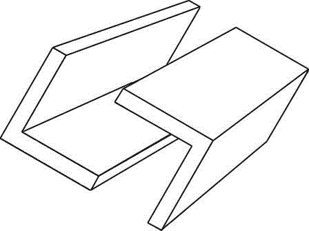
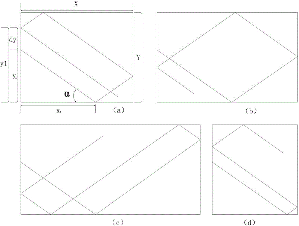
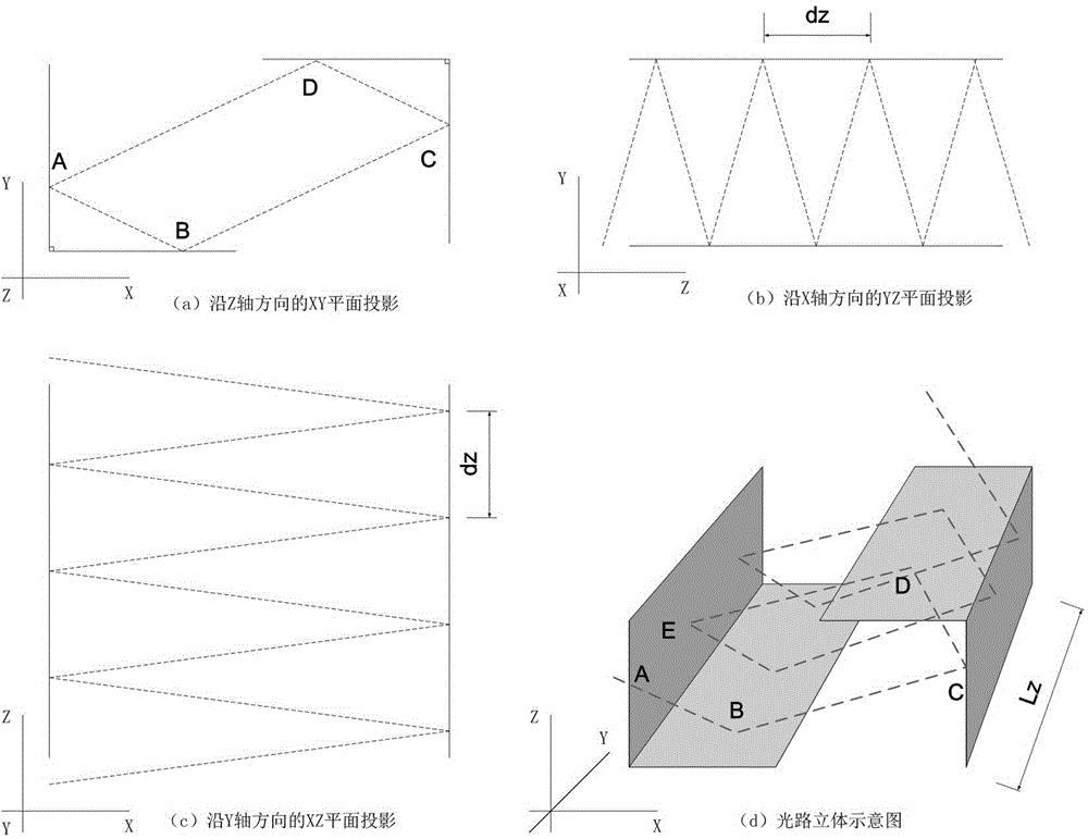
[0019] Such as Figure 1-3 As shown, an optical air chamber includes an air chamber cavity module and a plane reflection module, the plane reflection module forms a square structure with two ends open, the adjacent sides of the square structure are perpendicular to each other, and the square The body structure is fixed by the gas chamber cavity module, and the gas chamber module provides test gas. The gas chamber cavity module is a substantially closed structure, and the exit of light, the exit of light, the exit of gas and the gas The outlet; the gas can be exchanged by diffusion ...


PUM


Abstract

The invention provides an optical gas chamber and a method for calculating the total optical distance by the gas chamber, relating to the field of measurement on gas components by a light ray analyzer. The optical gas chamber comprises a gas chamber cavity module and a plane reflection module, wherein the plane reflection module forms a square structure with openings in two ends, the adjacent side surfaces of the square structure are mutually vertical, the square structure is fixed by the gas chamber cavity module which provides to-be-tested gas, a coordinate system is selected according to the shape of the gas chamber structure, and the total optical distance is calculated. The optical gas chamber is simple in structure; the total optical distance of light rays in gas can be effectively obtained by matching with a calculating method, the maximization of light paths in a small space is realized, and the problem of interference caused by overlapping of the light paths can be reduced.

Description

technical field [0001] The invention relates to the field of gas composition measurement by a light analyzer. Background technique [0002] At present, the gas chambers used in infrared analyzers mainly include straight-through gas chambers and multi-reflection gas chambers. The gas concentration can be detected by using the absorption or scattering of light by the gas; the straight-through gas chamber has a simple structure, The volume of the gas chamber is small and the reaction speed is fast. It is a commonly used method for high-concentration gas analysis in industry. However, the straight-through gas chamber is limited by the size of the standard case, so that the optical path does not exceed 20mm, so the straight-through gas chamber is limited to the measurement of high-concentration gases. The principle of reflection increases the optical path, thereby increasing the optical depth, but due to the structure of the air chamber, the optical path of the existing multiple...

Claims


Application Information

Patent Timeline
Patent Type & Authority Applications(China)
IPC IPC(8): G01N21/01
Inventor 刘明黄贵玉
Owner DONGGUAN INST OF OPTO ELECTRONICS PEKING UNIV
Learn More