
Spinning type hydrogen backflow device

A reflow device and spin-type technology, applied in the field of reflow, can solve the problems of unsatisfactory ejection efficiency, waste and high energy consumption of the ejector, and achieve the effect of poor solution and controllable and effective suction force.

Inactive Publication Date: 2021-07-20
SHANGHAI ELECTRICGROUP CORP
View PDF5 Cites 0 Cited by
  • Summary
  • Abstract
  • Description
  • Claims
  • Application Information

AI Technical Summary

Problems solved by technology

In order to ensure the normal progress of the fuel cell reaction, a certain excess of hydrogen will be provided, so some hydrogen will not participate in the reaction. If the unreacted hydrogen is directly discharged into the atmosphere, it is both a pollution and a waste, so hydrogen must be added to the system circulation device
[0003] In the existing technology, in order to ensure the normal progress of the fuel cell reaction, a certain amount of hydrogen will be provided. The unreacted hydrogen of the stack cannot be directly discharged out of the system. It needs to be combined with the inlet hydrogen and returned to the fuel cell to increase the hydrogen utilization rate. Although the pump cycle is adopted It can improve the hydrogen circulation, but the energy consumption is high, the control system is complicated, and the injection efficiency of the ejector in the low power state is not ideal

Method used


Image

  • Spinning type hydrogen backflow device
  • Spinning type hydrogen backflow device
  • Spinning type hydrogen backflow device

Examples


Embodiment Construction

[0023] The technical solutions of the present invention will be clearly and completely described below in conjunction with the accompanying drawings. Apparently, the described embodiments are some of the embodiments of the present invention, but not all of them. Based on the embodiments of the present invention, all other embodiments obtained by persons of ordinary skill in the art without making creative efforts belong to the protection scope of the present invention.

[0024] In the description of the present invention, it should be noted that if the terms "center", "upper", "lower", "left", "right", "vertical", "horizontal", "inner", "outer" appear ", etc., the indicated orientation or positional relationship is based on the orientation or positional relationship shown in the drawings, which is only for the convenience of describing the present invention and simplifying the description, rather than indicating or implying that the referred device or element must have a specif...


PUM


Abstract

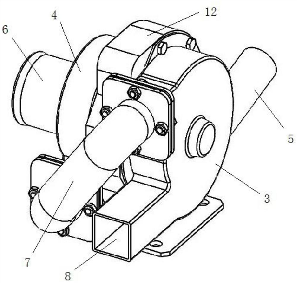
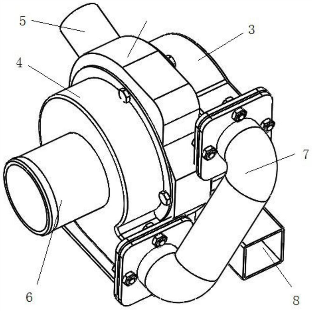
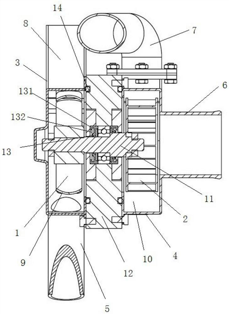
The invention discloses a self-rotating type hydrogen backflow device, and relates to the technical field of backflow, the self-rotating type hydrogen backflow device comprises a driving impeller, a centrifugal impeller, a first shell, a second shell, a main pipeline, a backflow pipeline and a connecting pipe, the first shell is connected with the second shell, the driving impeller is arranged in the first shell, the centrifugal impeller is arranged in the second shell, the driving impeller is in transmission connection with the centrifugal impeller, a main pipeline is arranged on one side of the first shell, an outlet is formed in the other side of the first shell, a backflow pipeline is arranged on one side of the second shell, and the first shell and the second shell are connected through the connecting pipe. According to the invention, airflow in the main pipeline pushes the driving impeller to rotate, the driving impeller drives the centrifugal impeller to rotate, and suction force is generated to ensure that airflow in the return pipeline converges into the main pipeline and is supplied to the electric pile for use; an additional power source is not needed structurally, and the mode is more reliable than the mode that suction force is generated through pure airflow; the problem that a fixed ejector is poor in effect in a low-power state can be solved.

Description

technical field [0001] The invention relates to the technical field of reflux, in particular to a spin-type hydrogen reflux device. Background technique [0002] In recent years, as environmental and energy issues have become increasingly prominent, various countries are scrambling to develop new forms of energy. Proton exchange membrane fuel cells have received more and more attention for their advantages of high efficiency and zero emissions. The fuel cell system includes an air subsystem, a hydrogen subsystem, a water heat management system, etc. The hydrogen subsystem provides high-purity hydrogen at a certain pressure and flow rate to the stack to ensure the normal chemical reaction of the fuel cell stack. In order to ensure the normal progress of the fuel cell reaction, a certain excess of hydrogen will be provided, so some hydrogen will not participate in the reaction. If the unreacted hydrogen is directly discharged into the atmosphere, it is both a pollution and a w...

Claims


Application Information

Patent Timeline
IPC IPC(8): H01M8/04089
CPCH01M8/04097Y02E60/50
Inventor 王兵杨敏季文姣杨建波
Owner SHANGHAI ELECTRICGROUP CORP
Learn More