
Monocular binocular telescope

A telescope and binocular technology, applied in the field of telescopes, can solve the problems of complex structure of telescopes, increase of product manufacturing costs, etc., and achieve the effects of facilitating large-scale popularization and application, reducing components, and low manufacturing costs

Active Publication Date: 2006-10-18
陇涤湘 +1
View PDF1 Cites 0 Cited by
  • Summary
  • Abstract
  • Description
  • Claims
  • Application Information

AI Technical Summary

Problems solved by technology

However, the structure of this kind of telescope is complicated, and the spectroscopic device needs to add four prisms, which greatly increases the manufacturing cost of the product, and is not suitable for popularization and application on products such as astronomical telescopes and target mirrors with large demand.

Method used


Image

  • Monocular binocular telescope
  • Monocular binocular telescope
  • Monocular binocular telescope

Examples


Embodiment 1

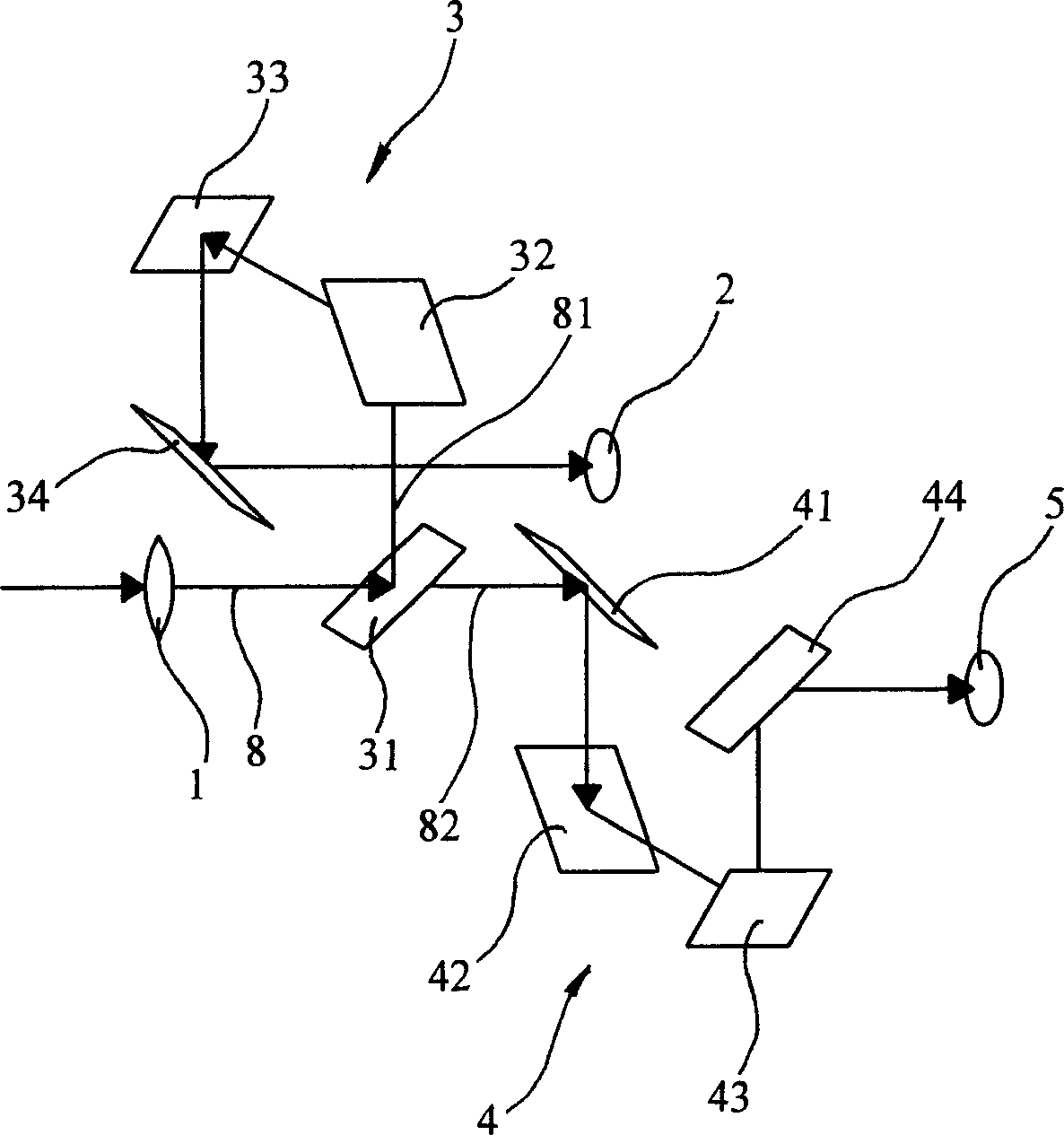
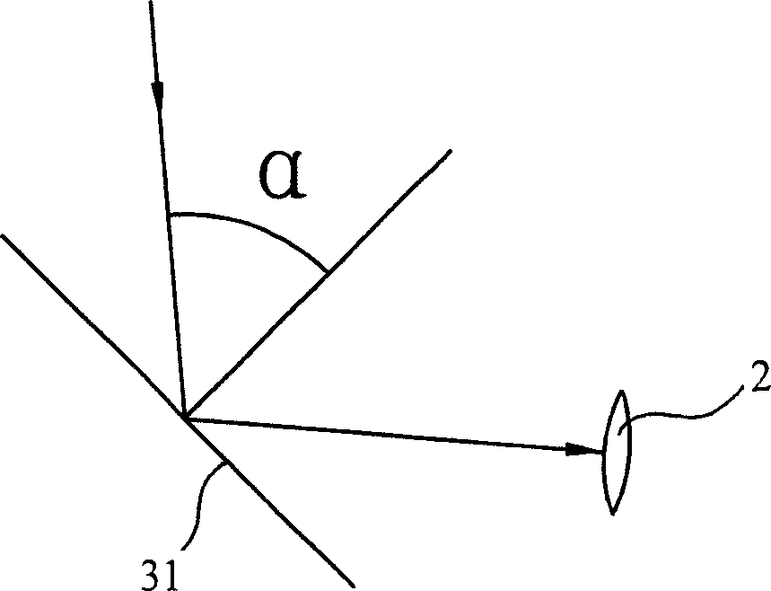
[0019] Embodiment one: a kind of monocular binocular observation telescope, comprise objective lens 1, the first eyepiece 2 and the first transfer mechanism 3, the first transfer mechanism 3 comprises the first plane reflector 31, the second plane reflector 32, The third plane reflector 33 and the fourth plane reflector 34, the incident surface of the first plane reflector 31 is perpendicular to the incident surface of the second plane reflector 32, the incident surface of the second reflector 32 is perpendicular to the incident surface of the third reflector 33 The incident planes coincide with each other, the incident plane of the third reflecting mirror 33 and the incident plane of the fourth reflecting mirror 34 are perpendicular to each other, the incident angle of the first reflecting mirror 31, the incident angle of the second reflecting mirror 32 and the third reflecting mirror 33 The angle of incidence is equal to 45 degrees, and the angle of incidence α of the fourth ...

Embodiment 2

[0020] Embodiment two: other structures of this embodiment are the same as embodiment one, and the difference is that a first auxiliary reflector (not shown) is arranged between the first eyepiece 2 and the first transfer mechanism 3, and the second eyepiece 5 and A second auxiliary plane reflector (not shown) is arranged between the second transfer mechanism 4 , the incident angle α of the fourth plane reflector 34 is 45 degrees, and the first eyepiece 2 and the second eyepiece 5 are an astronomical observation eyepiece set.

Embodiment 3

[0021]Embodiment three: the structure of this embodiment is the same as that of embodiment one or embodiment two, the difference is that a spectroscopic device 10 is arranged between the objective lens 1 and the first transfer mechanism 3, and the optical path 8 through the objective lens 1 reaches the spectroscopic device Afterwards, a beam of light is split to the first transfer mechanism 3, and a beam of light is split to reach the third transfer mechanism 11. The structure and characteristics of the third transfer mechanism 11 are exactly the same as those of the first transfer mechanism 3, and the third transfer mechanism 11 reaches the third transfer mechanism. The light beam of the imaging mechanism 11 is divided into two paths, one reaches the third eyepiece 12, and the other reaches the fourth eyepiece 14 after passing through the fourth image transfer mechanism 13. The structure and characteristics of the image mechanism 15 are exactly the same as those of the first i...


PUM


Abstract

The invention discloses a monocular binocular observation telescope, which uses a rotating image mechanism composed of four reflecting mirrors forming a certain angle with each other to replace the image rotating mechanism composed of prisms, greatly reduces the production cost of the product, and ingeniously Taking advantage of the characteristics of this relay mechanism, the first plane mirror is set as a semi-transparent mirror, so that it has the functions of image relay and light splitting at the same time, which greatly simplifies the structure of the product and reduces the number of parts of the product. , at this time, a second transfer mechanism with the same structure and an eyepiece are arranged behind the semi-transparent mirror, so that the purpose of binocular observation on the monocular can be realized, and the product structure is simple and the product manufacturing cost is low. , the advantages of light weight and small volume, compared with the similar monocular binocular telescope made with prism, the manufacturing cost of the present invention is only one thousandth of its manufacturing cost, which is convenient for wide-scale popularization and application.

Description

technical field [0001] The invention relates to a telescope, in particular to a monocular binocular observation telescope. Background technique [0002] Existing optical telescopes are mainly used for magnified observation of distant objects, and their types mainly include monoculars and binoculars. A telescope generally includes an objective lens, an eyepiece, and an image transfer mechanism arranged between the objective lens and the eyepiece. These image transfer mechanisms are generally composed of more than two prisms. The processing requirements of the image transfer mechanism composed of such prisms are relatively high. The prism itself The weight is also relatively heavy, and the cost of product quality is relatively high. In a telescope, the cost of the image transfer mechanism accounts for a large proportion. In people's daily use, due to the large size of the binoculars, and the defects of heavy weight and relatively high cost caused by many parts, people are usi...

Claims


Application Information

Patent Timeline
Patent Type & Authority Patents(China)
IPC IPC(8): G02B23/00G02B5/08G02B27/10G02B7/12G02B17/06G02B23/18G02B25/00
CPCG02B7/12G02B17/026G02B23/18
Inventor 陇涤湘应斐
Owner 陇涤湘
Learn More