
Cable laying robot

A cable laying and robot technology, applied in the direction of cable laying equipment, etc., can solve the problems of inconvenient operation, difficulty, and difficult cable laying, etc., and achieve the effect of simple and convenient process, simple structure and easy realization.

Active Publication Date: 2015-07-15
WUHAN UNIV OF TECH
View PDF5 Cites 11 Cited by
  • Summary
  • Abstract
  • Description
  • Claims
  • Application Information

AI Technical Summary

Problems solved by technology

[0003] At present, the traditional manual method is mostly used for cable laying, which is inconvenient to operate, especially when the cable length exceeds 100-200 meters, because the pipeline is too long, bent, and the cable diameter and weight are large, if the cable is pulled by manpower It is very difficult to go through the pipeline
At present, the mechanical traction method is generally used, but this method cannot complete long-distance cable laying, and many problems will occur during the traction process
Later, in response to these problems of the mechanical traction method, the "air blowing laying" method appeared again, but "air blowing laying" is difficult to complete the laying of thicker cables, and is often used for the laying of optical cables.

Method used


Image

  • Cable laying robot
  • Cable laying robot
  • Cable laying robot

Examples


Embodiment Construction

[0028] It should be understood that the specific embodiments described here are only used to explain the present invention, not to limit the present invention.

[0029] It should be noted that, in the description of the present invention, the terms "horizontal", "vertical", "upper", "lower", "front", "rear", "left", "right", "vertical", The orientation or positional relationship indicated by "horizontal", "top", "bottom", "inner", "outer", etc. is based on the orientation or positional relationship shown in the drawings, and is only for the convenience of describing the present invention and simplifying the description, and It is not to indicate or imply that the device or element referred to must have a particular orientation, be constructed in a particular orientation, or operate in a particular orientation, and thus should not be construed as limiting the invention. In addition, the terms "first", "second", etc. are used for descriptive purposes only, and should not be cons...


PUM


Abstract

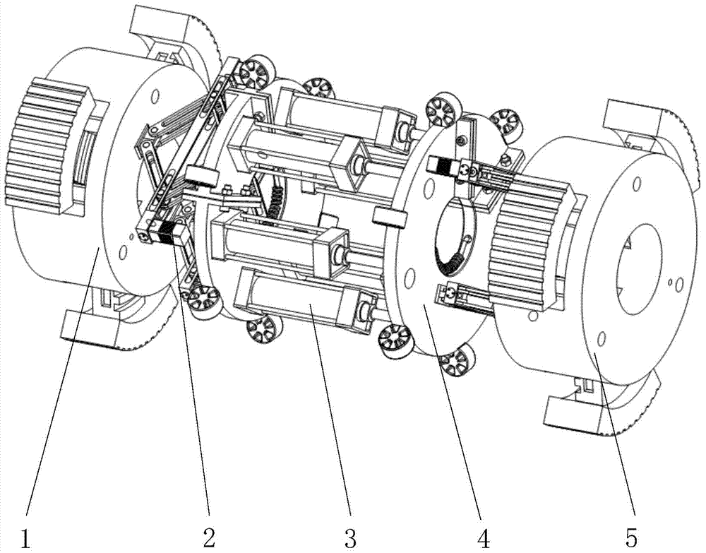
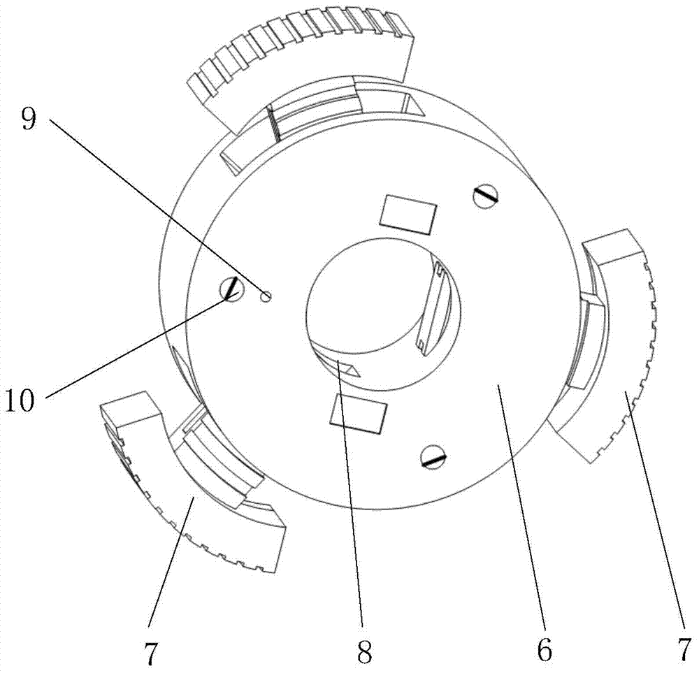
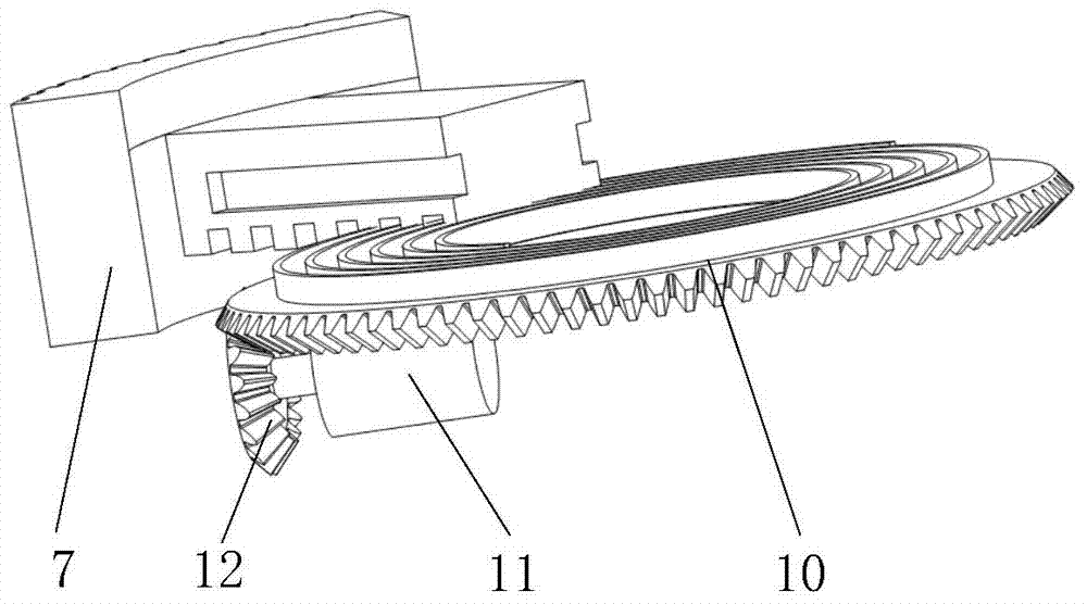
The invention discloses a cable laying robot. The cable laying robot comprises a first top wall mechanism, a first fork shearing push mechanism, a passive type pseudo parallel steering mechanism, a second fork shearing push mechanism and a second top wall mechanism which are connected in sequence, wherein the first top wall mechanism and the second top wall mechanism comprise chuck bodies, top wall supports which are installed on the chuck bodies and can move in an extension mode relative to the radial directions of the chuck bodies and first driving mechanisms, a second driving mechanism used for driving the first fork shearing push mechanism to move in an extension mode relative to the first top wall mechanism is arranged on the first fork shearing push mechanism, the passive type pseudo parallel steering mechanism comprises two subdivision chassis which are arranged oppositely and a steering mechanism, the subdivision chassis are arranged outside a cable in a sleeved mode, and a third driving mechanism used for driving the second fork shearing push mechanism to move in an extension mode relative to the second top wall mechanism is arranged on the second fork shearing push mechanism. The cable laying robot can creep in various pipelines such as a horizontal pipeline, or a vertical pipeline or an inclined pipeline, laying of the cable is achieved, and the cable laying robot cannot be limited by the thickness and the length of the cable.

Description

technical field [0001] The invention relates to the technical field of cable laying auxiliary equipment, in particular to a cable laying robot. Background technique [0002] In recent years, with the rapid development of the economy, the pace of urban construction in my country is also getting faster and faster, and the urban electricity load is increasing rapidly, which puts forward higher and higher requirements for the reliability of power supply. At the same time, urban planning and construction and beautiful city appearance have gradually attracted the attention of the society. Therefore, today's urban construction uses cable lines to enter the ground. In the cable line project, the power cable is laid underground without occupying the ground space, which is conducive to the appearance of the city and the safety of life; the natural environment such as lightning, wind and rain, salt spray, pollution, etc. has little impact on the cable, and the reliability of cable powe...

Claims


Application Information

Patent Timeline
IPC IPC(8): H02G1/06
Inventor 李波刘思毫胡镔江强孙沛泽吴天遥陈定方
Owner WUHAN UNIV OF TECH
Learn More