

LED lighting device and LED lighting device with electricity consumption calculating function
A technology of LED lighting and power consumption, applied in the field of LED lighting, can solve the problems of power consumption error, inability to determine the power consumption of each module, and uncertain power consumption, etc., to achieve the effect of accurate power consumption
- Summary
- Abstract
- Description
- Claims
- Application Information
AI Technical Summary
Problems solved by technology
Method used
Image

Examples
Embodiment Construction
[0029] A detailed description will be given below in conjunction with the accompanying drawings.
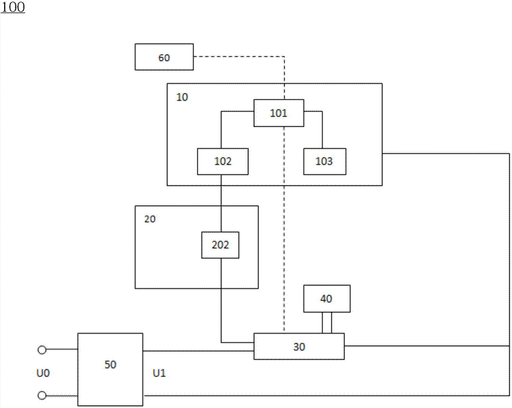
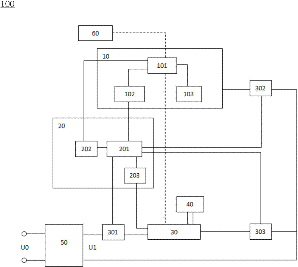
[0030] Such as figure 1As shown, the present invention provides an LED lighting device. The LED lighting device includes a wireless communication relay device 10 , a light source driving module 30 , a control unit 20 and a light source module 40 . The LED lighting device further includes a power module 50 . In the present invention, a preset power value is pre-stored in the control unit 20 for each working state of the light source module 40 . The light source driving module 30 is integrated and / or connected to the light source module 40, and the light source driving module 30 is used for adjusting the color temperature and brightness of the light source module 40, and turning on or off the light source module. The preset power value further includes the power values of the light source driving module 30 and the wireless communication relay device 10 . By testing the light ...
PUM
 Abstract
Description
Claims
Application Information