Monitor device for a lighting arrangement, a driver using the monitoring arrangement, and a driving method

a monitoring device and lighting arrangement technology, applied in lighting devices, electrical devices, light sources, etc., can solve problems such as visual flashing, power supply voltage dips, and light load drawing more curren

Active Publication Date: 2022-07-19
SIGNIFY HLDG BV
View PDF13 Cites 2 Cited by
  • Summary
  • Abstract
  • Description
  • Claims
  • Application Information

AI Technical Summary

Benefits of technology

[0021]This monitoring device is able to determine the characteristics of the load using at least a cable resistance between a power supply unit and the lighting arrangement, so that the power consumption can be determined and also without individually driving each sub-set of lighting elements. The cable resistance is used in the determination of the power consumption downstream of the power supply unit.
[0083]These electrical characteristics or parameters enable the light output performance of the sub-set of lighting elements to be determined more accurately in response to a given set of duty cycle commands, and enable the overall power consumption to be determined more accurately.

Problems solved by technology

The disadvantage of such a voltage-based lighting system is that the lighting load can draw more current than the rated power of the power supply.
However, this results in visual flashing.
Moreover sudden load steps might result in voltage dips of the power supply.
In some voltage-based systems, a dip in voltage translates into a dip in current and hence the current is not well probed and the actual power is then not estimated correctly.
Measuring current while not having a constant DC voltage of e.g. 24V (while assuming it is a fixed value of 24V) causes a measurement error.

Method used


Image

  • Monitor device for a lighting arrangement, a driver using the monitoring arrangement, and a driving method
  • Monitor device for a lighting arrangement, a driver using the monitoring arrangement, and a driving method
  • Monitor device for a lighting arrangement, a driver using the monitoring arrangement, and a driving method

Examples


Embodiment Construction

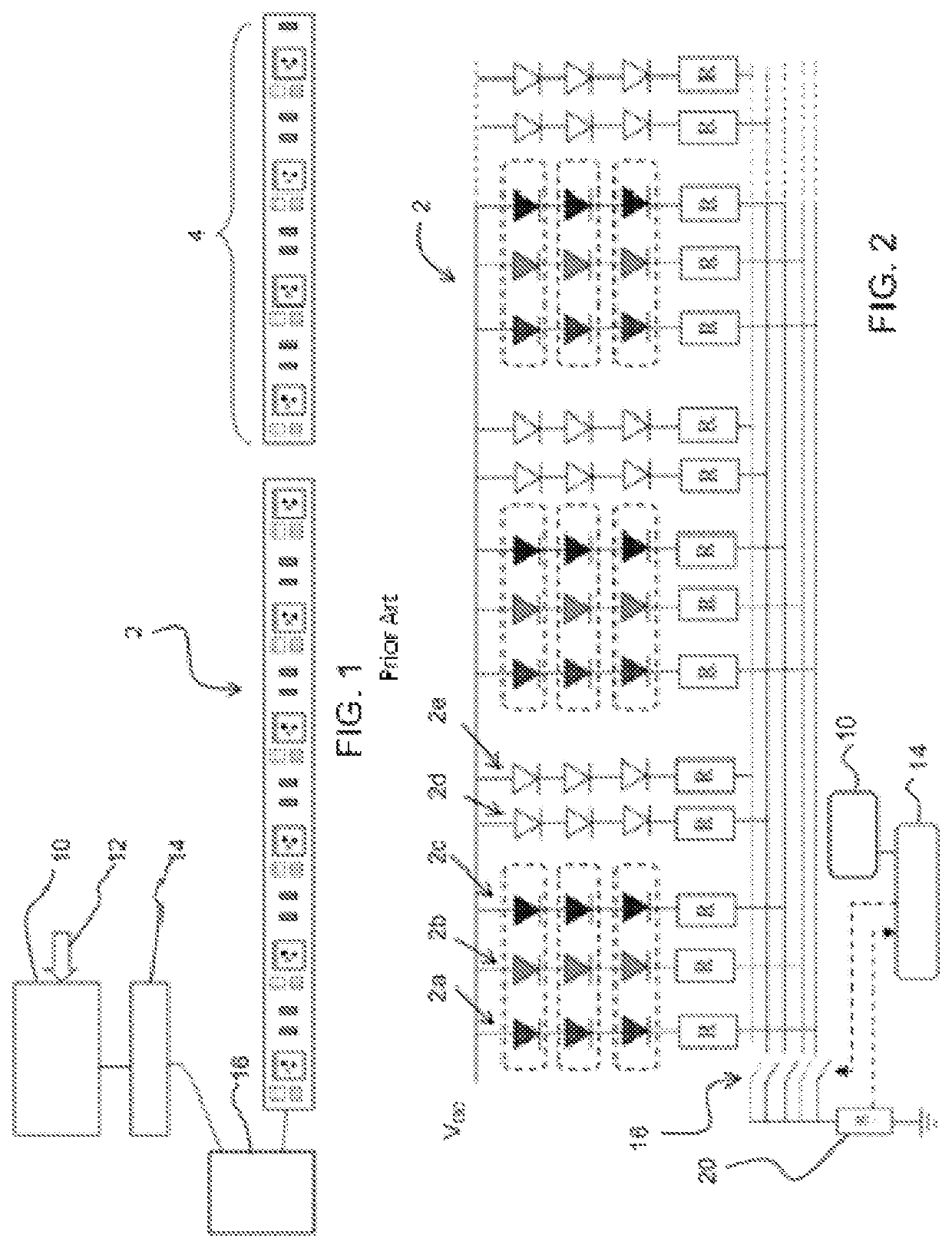
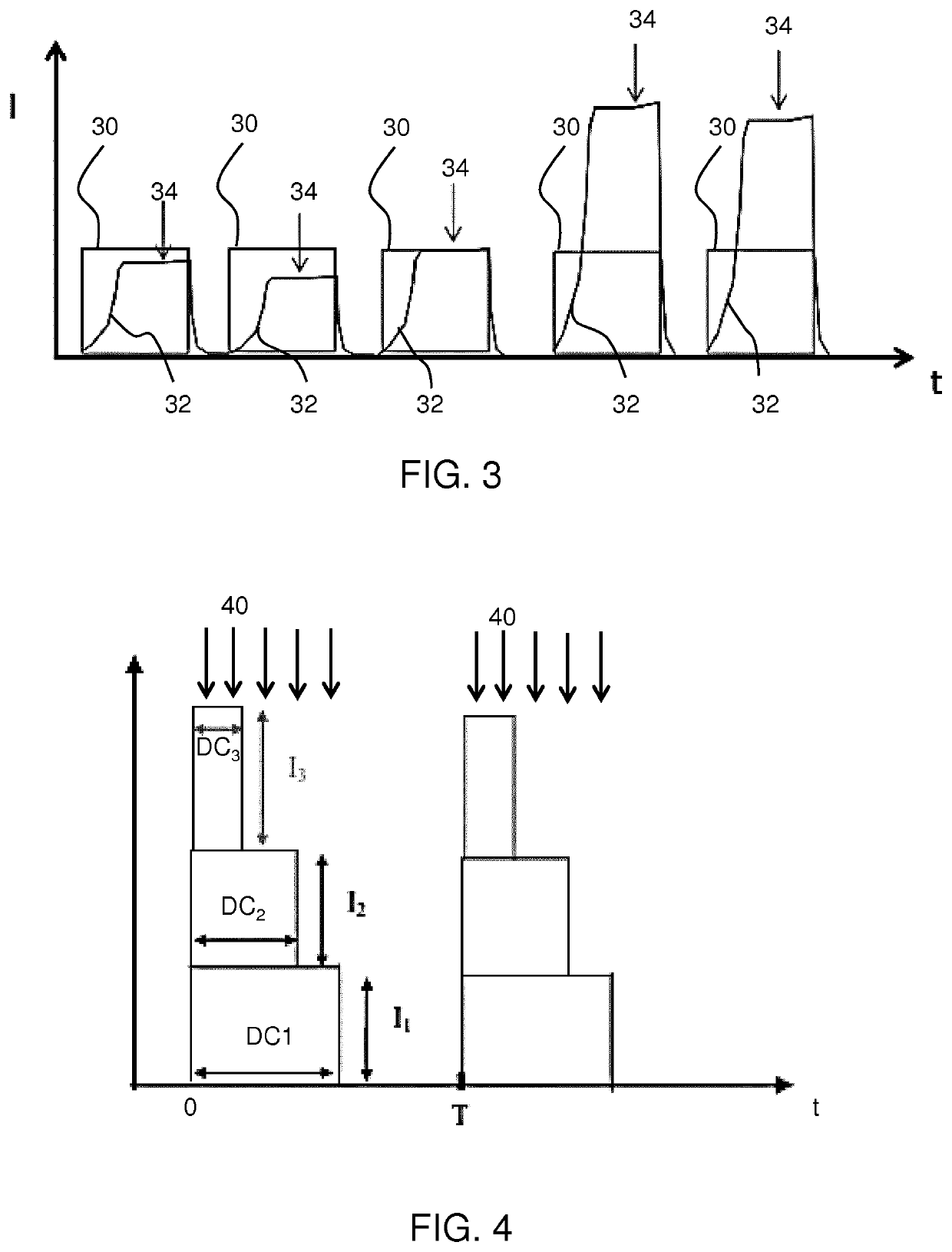
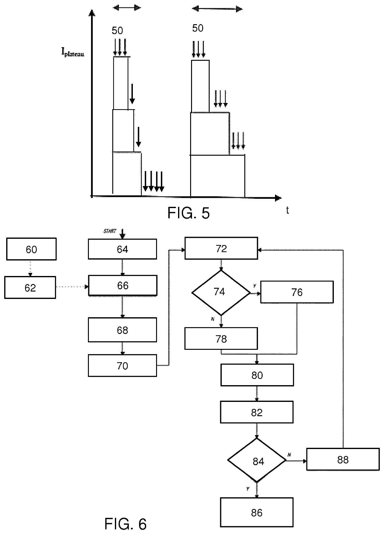
[0103]The invention provides a monitor device for monitoring a lighting arrangement of lighting elements of unknown electrical load, and a driver using the monitoring arrangement. A set of duty cycles is applied to switches which control sub-sets of lighting elements thereby to create a desired light output (i.e. desired by a user, and applied as a user input). With this desired duty cycle setting, the current for an individual duty cycle period is monitored, in particular to detect variations in a current plateau level within the individual duty cycle period. This is used to determine electrical characteristics including at least a cable resistance between a power supply unit and the lighting arrangement. An accurate estimation of the power consumption of the lighting arrangement (or more generally the load downstream of a power supply unit) may then be obtained. This avoids the need to probe the sub-sets of lighting elements individually in order to determine the nature of the loa...


PUM


Abstract

A monitor device is provided for monitoring a lighting arrangement of lighting elements of unknown electrical load, and a driver using the monitoring arrangement. A set of duty cycles is applied to switches which control sub-sets of lighting elements thereby to create a desired light output. With this desired duty cycle setting, the current for an individual duty cycle period is monitored, in particular to detect variations in a current plateau level within the individual duty cycle period. This is used to determine electrical characteristics or parameters including at least a cable resistance between a power supply unit and the lighting arrangement. A power consumption of the lighting arrangement may then be obtained. This avoids the need to probe the sub-sets of lighting elements individually in order to determine the nature of the load and its power consumption.

Description

CROSS-REFERENCE TO PRIOR APPLICATIONS[0001]This application is the U.S. National Phase application under 35 U.S.C. § 371 of International Application No. PCT / EP2019 / 064796, filed on Jun. 6, 2019, which claims the benefit of European Patent Application No. 18177760.8, filed on Jun. 14, 2018. These applications are hereby incorporated by reference herein.FIELD OF THE INVENTION[0002]This invention relates to a monitor device for monitoring a lighting arrangement and in particular in which the lighting load is unknown, for example because it is configurable by an end-user. The monitoring may then be used as part of driving of the lighting arrangement, thus being part of a controller or driver.BACKGROUND OF THE INVENTION[0003]There is a desire to be able to connect different lighting configurations to a standard driver design.[0004]For scalability reasons in lighting systems in which the load may vary, it is beneficial to work with a voltage architecture instead of a current source archi...

Claims


Application Information

Patent Timeline
Patent Type & Authority Patents(United States)
IPC IPC(8): H05B45/24H05B45/325H05B45/46H05B45/355H05B44/00
CPCH05B45/46H05B45/24H05B45/325H05B45/355
Inventor SQUILLACE, JORGE GABRIELHAGELAAR, JORIS HUBERTUS ANTONIUSSEVO, ALEKSANDARVOGELS, LUCAS LOUIS MARIEVAN DER HAM, MARCEL
Owner SIGNIFY HLDG BV
Why Eureka
Try Eureka