Audio signal coding device and audio signal decoding device

An audio signal encoding and audio signal technology, which is applied in the field of audio signal encoding devices and audio signal decoding devices, can solve problems such as gaps in reproduced signals, picture pauses, and sound interruptions

Inactive Publication Date: 2015-07-15
SOCIONEXT INC
View PDF7 Cites 0 Cited by
  • Summary
  • Abstract
  • Description
  • Claims
  • Application Information

AI Technical Summary

Problems solved by technology

Therefore, when the transmission path is mixed, since the transmitted audio and video signals cannot be transmitted in real time, gaps often occur in the reproduced signal.
For example, there may be interruptions in the sound, or a dead time such as a pause in the screen

Method used


Image

  • Audio signal coding device and audio signal decoding device
  • Audio signal coding device and audio signal decoding device
  • Audio signal coding device and audio signal decoding device

Examples


Embodiment approach 1

[0073] Hereinafter, an audio signal encoding device and an audio signal decoding device according to Embodiment 1 of the present application will be described with reference to the drawings.

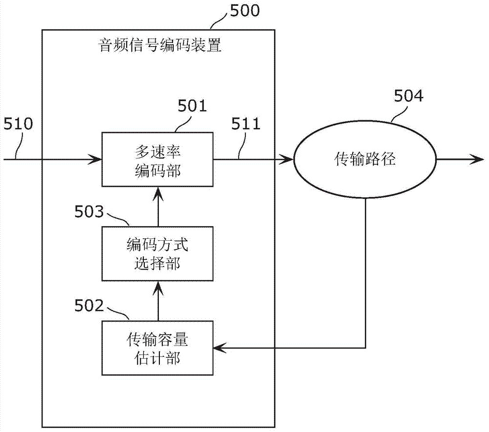
[0074] The audio signal encoding device according to the present embodiment changes the boundary frequency used for division according to the transmission capacity of the transmission line. Accordingly, the audio signal encoding device can appropriately cope with fluctuations in the transmission capacity of the transmission path.

[0075] First, the configuration of the audio signal transmission system 100 according to the present embodiment will be described.

[0076] Figure 5 It is a block diagram showing the configuration of the audio signal transmission system 100 according to this embodiment. figure 1The illustrated audio signal transmission system 100 includes: an audio signal encoding device 200 (transmitting device), an audio signal decoding device 300 (receiving device), and ...

Embodiment approach 2

[0148] In Embodiment 1 described above, the number of channels of the input audio signal 250 is not limited. The input audio signal 250 can be 1ch signal, 2ch signal, 5.1ch signal, 7.1ch signal, or any other number of channels. In this case, it is only necessary to perform the above-mentioned processing on the signals of each channel.

[0149] In addition, in order to enhance the tracking of the variation of the transmission capacity of the transmission path, that is to say, in order not to cause sound discontinuity even when the transmission capacity is more embarrassing, the correlation between channels can be used to analyze the down-mixed signal Apply up-mixing techniques.

[0150] In this embodiment, a case where such down-mixing and up-mixing are used will be described.

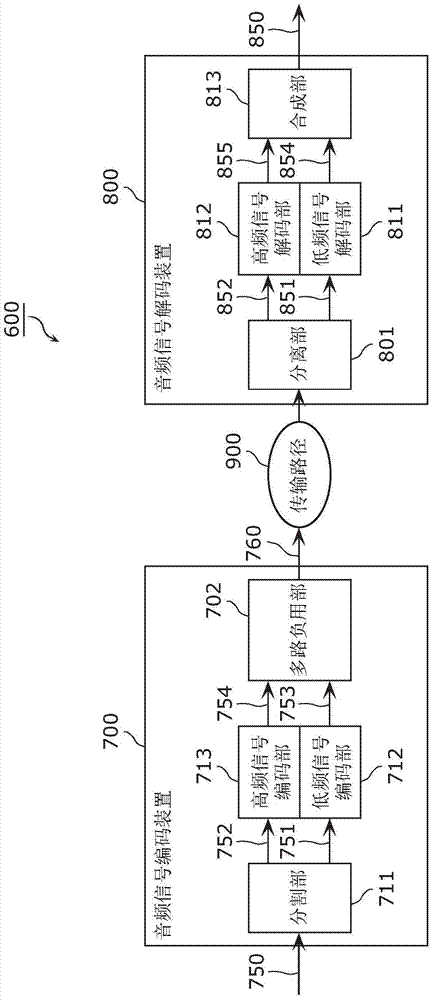
[0151] Figure 12 It is a block diagram of an audio signal encoding device 200A according to this embodiment. And, for Figure 6 The same reference numerals are given to the same elements, and the ...


PUM


Abstract

An audio signal coding device (200) is provided with: a hierarchical coding unit (201) which generates a low-frequency coded signal (253) by coding a low-frequency signal (251) in a lower frequency range than a boundary frequency and generates a high-frequency coded signal (254) by coding a high-frequency signal (252) in a higher frequency range than the boundary frequency, the low-frequency signal and the high-frequency signal being included in an input audio signal (250); and a hierarchical boundary setting unit (204) which, when a coding bit rate used for the coding by the hierarchical coding unit (201) is a first bit rate, sets the boundary frequency to a first frequency, and when the coding bit rate is a second bit rate lower than the first bit rate, sets the boundary frequency to a second frequency lower than the first frequency.

Description

technical field [0001] The present application relates to an audio signal encoding device that generates an encoded audio signal by encoding an input audio signal, and an audio signal decoding device that decodes the encoded audio signal. Background technique [0002] In recent years, systems for distributing audio and video signals using digital networks have been widely used. For example, services such as YouTube (Youku, a registered trademark) can be performed to distribute audio and video signals from a server installed in a remote place. Also, in recent years, video conferencing systems that communicate high-quality audio and video signals have been increasingly popular. [0003] The transmission capacity of transmission paths for transmitting these digital signals is also expanding year by year. However, the aforementioned increase in the transmission volume of audio and video signals has already exceeded the transmission capacity. Accordingly, the necessity of comp...

Claims


Application Information

Patent Timeline
IPC IPC(8): G10L19/008G10L19/24G10L19/02
CPCG10L19/0204G10L19/24G10L19/008H03M7/3059
Inventor 宫阪修二沈荣辉
Owner SOCIONEXT INC
Why Eureka
Try Eureka