Flywheel clutch positioning pin pressing tool

A press-fit tooling and positioning pin technology, applied in metal processing, manufacturing tools, metal processing equipment, etc., can solve the problems of laborious operation for workers and low press-fit efficiency, and achieve good reliability, simple structure and good practicability Effect

Active Publication Date: 2015-07-22
绿驰智能(深圳)有限公司
View PDF6 Cites 17 Cited by
  • Summary
  • Abstract
  • Description
  • Claims
  • Application Information

AI Technical Summary

Problems solved by technology

[0002] The clutch positioning pin is an important part of the flywheel. At present, it is generally press-fitted on the flywheel by manual methods. The disadvantage of this press-fitting method is that the press-fitting efficiency is low and the workers are laborious to operate.

Method used


Image

  • Flywheel clutch positioning pin pressing tool
  • Flywheel clutch positioning pin pressing tool
  • Flywheel clutch positioning pin pressing tool

Examples


Embodiment Construction

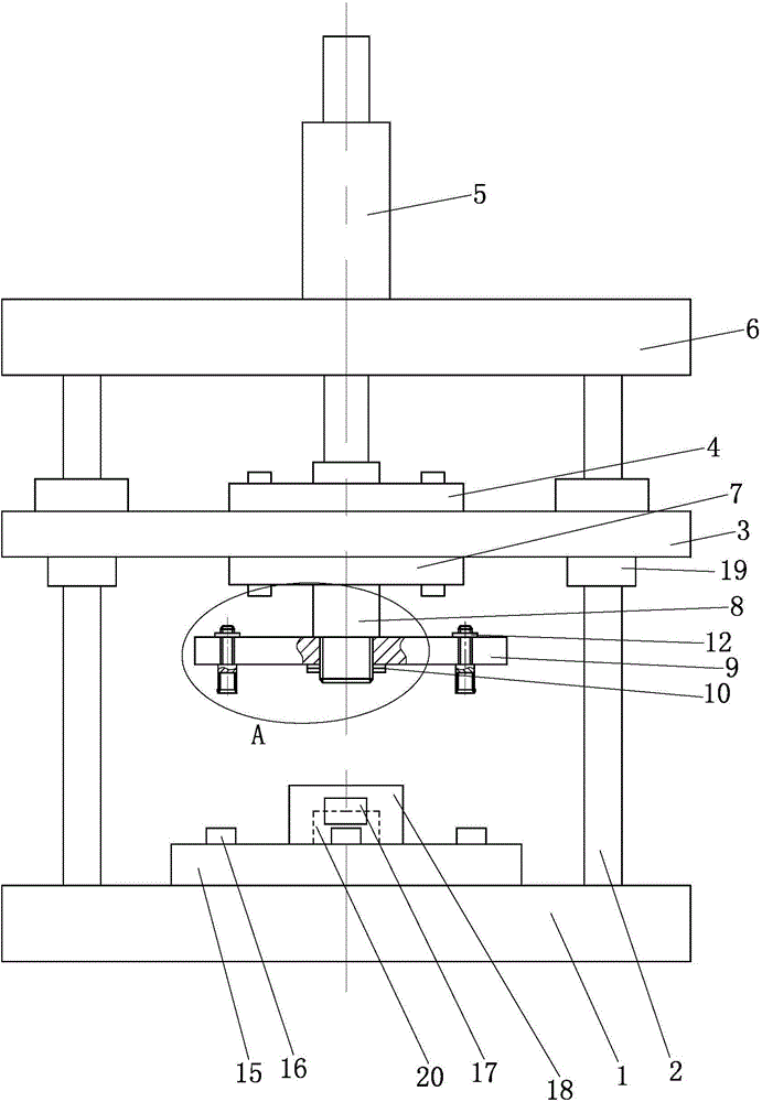
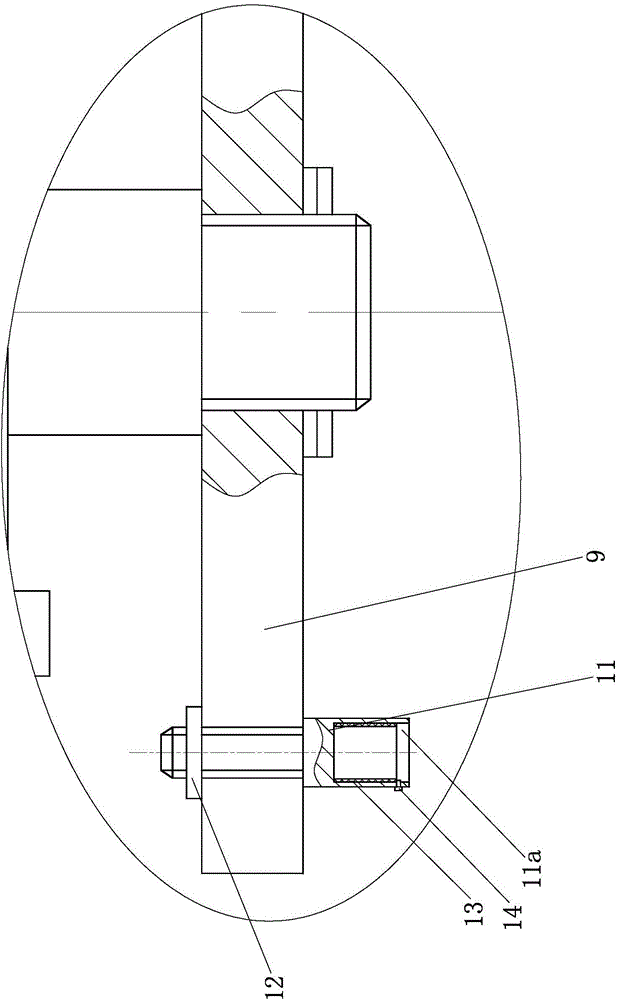
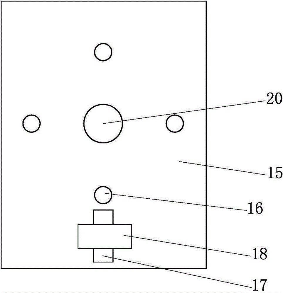
[0014] Below in conjunction with accompanying drawing and embodiment the present invention will be further described:

[0015] Such as figure 1 , 2 , 3, a flywheel clutch positioning pin pressing tool, mainly by the base 1, column 2, horizontal movable plate 3, upper connection plate 4, cylinder 5, top plate 6, lower connection plate 7, vertical shaft 8, press Disk 9, double nut 10, positioning pin connecting rod 11, lock nut 12, rubber sleeve 13, radial screw 14, backing plate 15, positioning pad 16, circumferential positioning block 17, mounting seat 18, sliding bearing 19 and The central positioning column 20 constitutes. Wherein, four columns 2 are fixedly arranged on the top surface of the base 1, and these four columns 2 are distributed on the four vertices of the same rectangle, and a horizontal movable plate 3 is connected between these four columns 2, and the horizontal movable Plate 3 is in sliding fit with column 2 . In this case, four sliding bearings 19 are in...


PUM


Abstract

The invention discloses a flywheel clutch positioning pin pressing tool. Four stand columns are fixedly arranged on the top face of a base, and a horizontal movable plate is connected among the four stand columns in a sliding mode. An upper connecting disc of the upper plate face of the horizontal movable plate is fixed to the lower end of a piston rod of a cylinder. The cylinder is installed on a top plate. The bottom face of the top face is fixed to the top ends of the four stand columns. A vertical shaft is fixedly arranged on the lower disc face of a lower connecting disc of the lower plate face of the horizontal movable plate. The small-diameter section of the vertical shaft is sleeved with a pressing disc and a double nut. Positioning pin connecting rods are circumferentially distributed on the pressing disc. The lower ends of the large-diameter sections of the positioning pin connecting rods are provided with positioning pin installation blind holes. A base plate is placed on the base and provided with a central positioning column and a positioning cushion block. Circumferential positioning blocks are arranged around the central positioning column. Clutch positioning pins can be accurately and rapidly pressed in pin holes in a flywheel, the flywheel clutch positioning pin pressing tool is high in automation degree and high in reliability, the clutch positioning pins at different circumferential positions can be pressed by rotating the pressing disc, and therefore the application range of the flywheel clutch positioning pin pressing tool is enlarged.

Description

technical field [0001] The invention belongs to the field of flywheel assembly, and in particular relates to a tool for press-fitting a positioning pin of a flywheel clutch. Background technique [0002] The clutch positioning pin is an important part of the flywheel. At present, it is generally press-fitted on the flywheel manually. The disadvantage of this press-fitting method is that the press-fitting efficiency is low and the workers are laborious to operate. Contents of the invention [0003] The technical problem to be solved by the present invention is to provide an automatic press-fitting tool for positioning pins of flywheel clutches. [0004] The technical scheme of the present invention is as follows: a flywheel clutch positioning pin press-fitting tool, characterized in that it includes a base (1) and a backing plate (15), wherein four columns (2) are fixed on the top surface of the base (1) ), these four columns are distributed on the four vertices of the sam...

Claims


Application Information

Patent Timeline
Patent Type & Authority Applications(China)
IPC IPC(8): B23P19/027
CPCB23P19/027
Inventor 廖长荣
Owner 绿驰智能(深圳)有限公司
Why Eureka
Try Eureka