
Air bag system

a technology of air bags and main body parts, which is applied in the direction of braking systems, pedestrian/occupant safety arrangements, tractors, etc., can solve the problems of not having a countermeasure to prevent the lateral deviation of the air bag towards the outside of the vehicle, and achieve the suppression of the movement of the inflatable main body portion, accurate suppression of the lateral deviation, and easy resistance to the effect of a lateral deviation

Inactive Publication Date: 2010-06-17
TOYODA GOSEI CO LTD
View PDF8 Cites 12 Cited by
  • Summary
  • Abstract
  • Description
  • Claims
  • Application Information

AI Technical Summary

Benefits of technology

[0011]The invention has been made with a view to solving the problems and an object thereof is to provide an air bag system in which a lateral deviation of an air bag towards an outside of a vehicle is suppressed when the air bag is inflated completely for receiving a pedestrian, so as to cover a front side of a front pillar accurately.
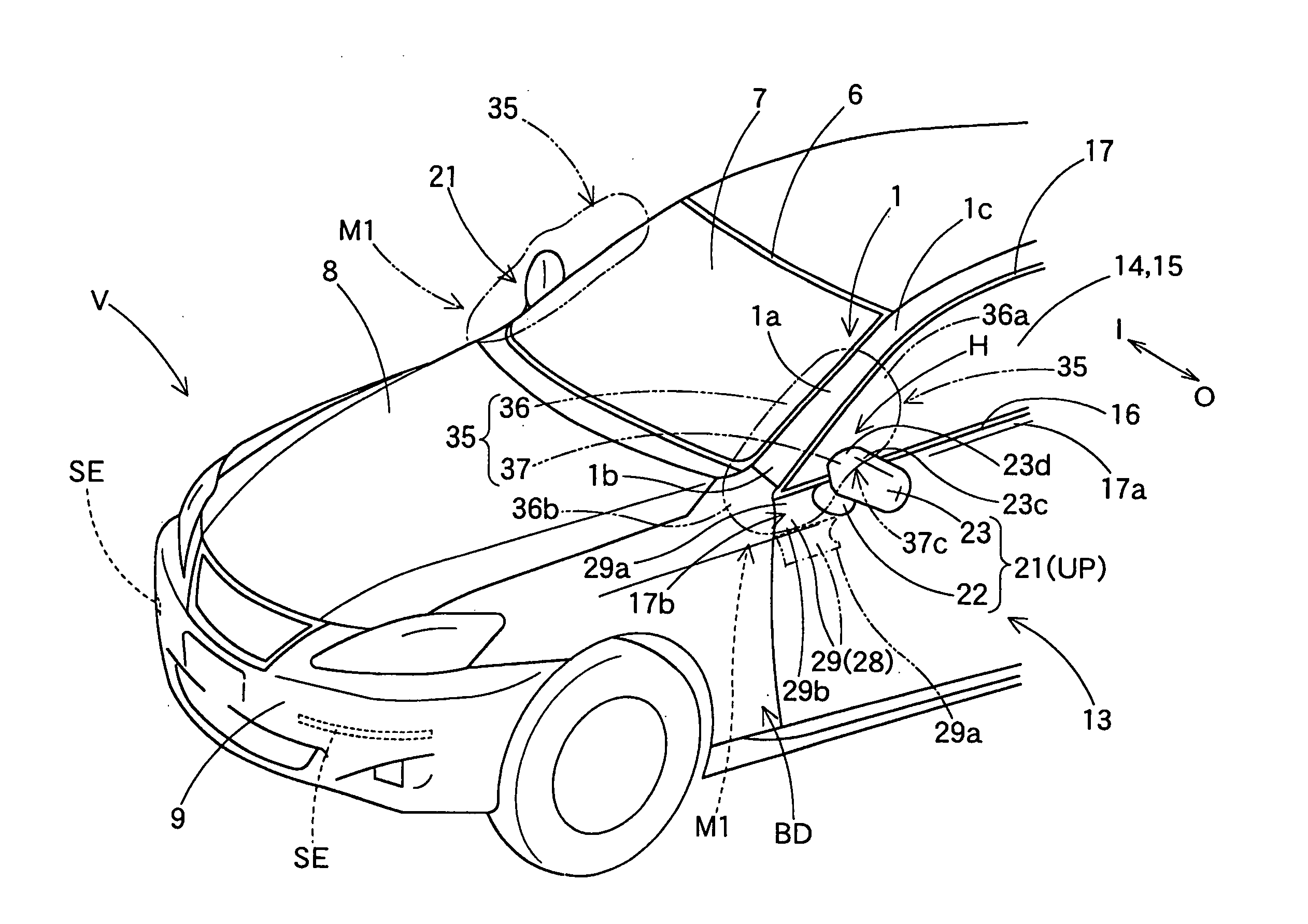
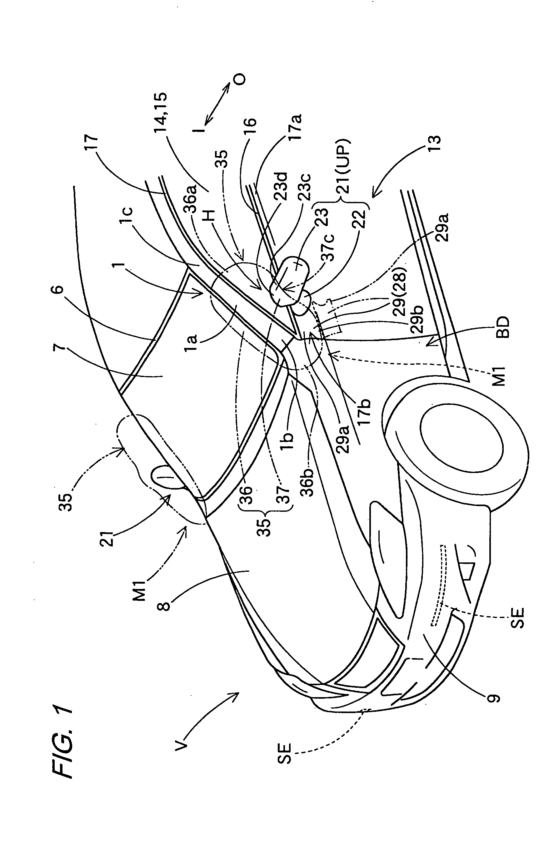
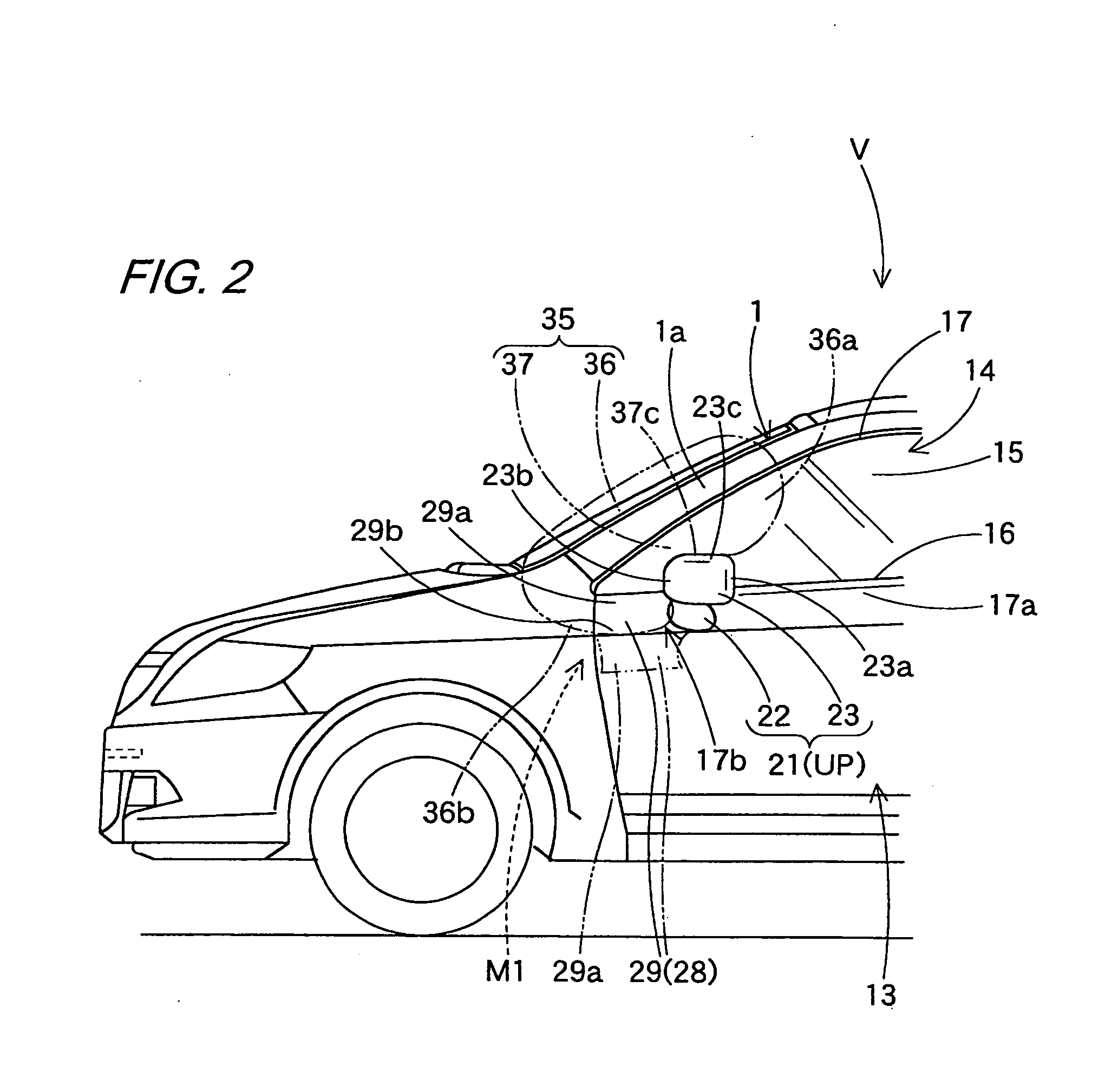
[0018]In the air bag system according to the invention, when activated, the air bag, which is folded to be stowed in proximity to the front side of the door mirror below the front pillar, is deployed to be inflated so as to cover the front surface of the front pillar. As this occurs, in the air bag, the inflatable main body portion covers the front surface of the front pillar, and the supporting inflatable portion, which is disposed to stretch continuously from the inflatable main body portion so as to extend from the inflatable main body portion towards the outside of the vehicle, is brought into abutment with the upper surface of the door mirror main body so as to be supported thereon. As this is happening, the vehicle is running and the mirror main body is in the usable position with the distal end extending towards the outside of the vehicle. Therefore, the upper surface of the mirror main body, with which a lower surface of the supporting inflatable portion is brought into abutment so as to be supported thereon, extends long towards the outside of the vehicle, and a sufficient reaction force can be secured to resist a pressing force acting on the supporting inflatable portion towards the outside of the vehicle by an area extending widely towards the outside of the vehicle. Because of this, for example, even when a pedestrian comes to interfere with the inflatable main body portion so as to push it from a windshield side to the outside of the vehicle, the supporting inflatable portion is supported on the upper surface of the mirror main body which extends long towards the outside of the vehicle and is prevented from moving. Thus, the supporting inflatable portion can support the inflatable main body portion so as to suppress a movement of the inflatable main body portion towards the outside of the vehicle accurately.
[0019]Furthermore, this supporting inflatable portion includes the lower surface which is supported on the upper surface of the mirror main body which extends towards the outside of the vehicle and is disposed in a portion which is spaced apart from the proximity to the front side of the door mirror below the front pillar which constitutes the stowage portion of the air bag, that is, an upper portion (a distal end side portion) which is spaced apart from a lower end (a front end) of the inflatable main body portion. This enables an accurate suppression of a lateral deviation of the inflatable main body portion towards the outside of the vehicle not by the portion in proximity to the lower end of the inflatable main body portion but by a distal end side (a rear end side) which lies apart from the lower end of the inflatable main body portion, in other words, a portion which is spaced apart from the lower end of the inflatable main body portion so as to easily resist a deviating movement of the inflatable main body portion, that is, the portion of the supporting inflatable portion that is supported on the upper surface of the mirror main body.
[0020]Consequently, in the air bag system according to the invention, the lateral deviation of the air bag towards the outside of the vehicle is suppressed when the air bag is inflated completely to receive a pedestrian, so as to cover the front surface of the front pillar accurately, thereby making it possible to preferably protect the pedestrian from the front pillar.
[0021]In the air bag system according to the invention, the supporting inflatable portion preferably fits in a gap defined between the mirror main body and the front side door of the vehicle. In addition, the air bag may be folded to be stowed in the front side door in a position which lies in proximity to a front side of the door mirror or may be folded to be stowed in a portion of a body of the vehicle which is positioned at a front of the front side door and in proximity to the front side of the door mirror. Incidentally, when the air bag is stowed in the front side door, the air bag is desirably stowed in an area around the mount base of the door mirror where a stowage space is easily secured. When the air bag is stowed in a portion on the body of the vehicle, compared with the case in which the air bag is stowed in an interior of the front side door where space available for the air bag is limited, the degree of freedom in layout of an inflator for supplying an inflation gas is enhanced, thereby making it possible to fixedly install the inflator in a stable fashion.

Problems solved by technology

However, there has been devised no countermeasure for preventing the lateral deviation of the air bag towards the outside of the vehicle.

Method used


Image

  • Air bag system
  • Air bag system
  • Air bag system

Examples


first embodiment

[0034]Hereinafter, an embodiment of the invention will be described based on the drawings. As is shown in FIGS. 1 to 4, an air bag system M1 of a first embodiment is installed in each of front side doors 13 which are disposed at a rear side of left and right front pillars 1 of a vehicle V consecutively. Each of the left and right front pillars 1 includes an outer panel 2, an inner panel 3 and a reinforcement 4 disposed between the outer panel 2 and the inner panel 3, and these panels are made of sheet steel. Thus, the front pillars 1 are provided while being given a high rigidity as a constituent member of the vehicle V (refer to FIG. 4). In FIG. 1, a member denoted by reference 6 is a window frame rubber, a member denoted by reference numeral 7 is a windshield, a member denoted by reference numeral 8 is a hood panel, and a member denoted by reference numeral 9 is a front bumper.

[0035]When used in this specification, directions denoted by such words as front, rear, up, down, left an...

second embodiment

[0050]In the air bag system M2 of the second embodiment, a stowage portion 26 for the air bag 35A and an inflator 31 is disposed in a panel portion 19A on an outside of the vehicle O which lies in proximity to a lower portion of a front pillar 1 at a front side of a window frame portion 17 of the front side door 13A. This panel portion 19A is disposed to stretch continuously from an outer panel 2 of the front pillar 1 and a portion of the panel portion 19 which lies at the front side of the window frame portion 17 is referred to as a mounting area 25 of the air bag system M2.

[0051]The air bag system M2 of the second embodiment includes the air bag 35A which is flexible and is formed into a bag-like shape, an inflator 31 for supplying an inflation gas into the air bag 35A, an air bag cover 28A which covers the air bag 35A which is folded while allowing it to project outwards and a retainer 32. Note that the inflator 31 and the retainer 32 are similar to those of the first embodiment,...


PUM


Abstract

An air bag system includes an air bag which can cover a front surface side of a front pillar of a vehicle. The air bag includes an inflatable main body portion and a supporting inflatable portion. The inflatable main body portion covers a front surface of the front pillar when the air bag is inflated completely. The supporting inflatable portion stretches continuously from the inflation main body portion so as to extend towards an outside of the vehicle from the inflation main body portion and is disposed to be brought into abutment with an upper surface of a mirror main body of a door mirror which is in a usable position on a lower surface side so as to be supported thereon to thereby support the inflatable main body portion, when the air bag is inflated completely.

Description

BACKGROUND OF THE INVENTION[0001]1. Field of the Invention[0002]The present invention relates to an air bag system which includes an air bag capable of covering a front surface side of a front pillar of a vehicle.[0003]2. Related Art[0004]There are various types of conventional air bag systems which are arranged so that an air bag is inflated so as to cover a front surface side of a front pillar of a vehicle to thereby prevent a pedestrian from being flung directly against the front pillar when the vehicle is involved in a collision with the pedestrian.[0005]In one of those air bag systems, a folded air bag is stowed in a recessed groove at a front surface side of a front pillar and is then covered with a resin garnish. When an inflator installed within the front pillar is activated to supply an inflation gas into the air bag therefrom, the air bag push opens the resin garnish and is deployed to be inflated so as to cover the front surface side of the front pillar (for example, refe...

Claims


Application Information

Patent Timeline
IPC IPC(8): B60R21/16B60R1/06B60R21/36B60R21/34
CPCB60R21/36
Inventor INOUE, MICHIOSUZUKI, SHIGEYUKI
Owner TOYODA GOSEI CO LTD
Learn More