Heat energy utilization method and heat energy utilization system in polycrystalline silicon production

A polysilicon and thermal energy technology, applied in the direction of silicon, sustainable manufacturing/processing, climate sustainability, etc., can solve the problems of increasing the production cost of polysilicon, not fully utilizing the thermal energy of the reduction furnace, and wasting thermal energy.

Active Publication Date: 2015-07-22
XINTE ENERGY
View PDF4 Cites 13 Cited by
  • Summary
  • Abstract
  • Description
  • Claims
  • Application Information

AI Technical Summary

Problems solved by technology

However, none of the above-mentioned processes make full use of the thermal energy generated in the production of the reduction furnace (used to produce polysilicon)
In the above several processes, the heat energy generated by high power consumption i

Method used


Image

  • Heat energy utilization method and heat energy utilization system in polycrystalline silicon production
  • Heat energy utilization method and heat energy utilization system in polycrystalline silicon production

Examples


Embodiment 1

[0077] This embodiment provides a method for utilizing heat energy in polysilicon production. This method is to send high-temperature return water from the reduction furnace system in polysilicon production into the flash system, and perform flash evaporation in the flash system, and then enter the flash system The temperature of the high-temperature return water is 145°C-160°C, the pressure is 0.5MPa-0.6MPa, and the low-pressure steam with a pressure of 0.175MPa-0.25MPa is flashed in the flash evaporation system, and the remaining The high-temperature water with a temperature of 128°C to 133°C is pressurized and then sent to the reduction furnace system to form high-temperature water for the reduction furnace system; the low-pressure steam from flash evaporation is sent to other equipment that needs steam in polysilicon production. The condensate obtained after exchanging heat with the other equipment is returned to the flash system.

[0078]Preferably, the temperature of the...

Embodiment 2

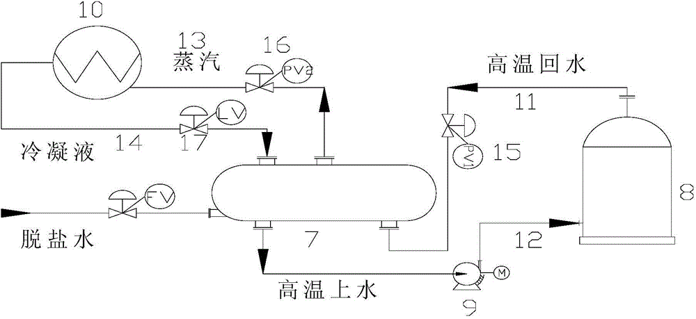
[0101] Please refer to figure 1 , figure 1 Specifically, it is a schematic diagram of a heat energy utilization method for polysilicon in this embodiment, which is mainly a comprehensive heat energy utilization method outside the reduction furnace system in the production process.

[0102] like figure 1 As shown, the thermal energy utilization method in the polysilicon production is to send the high-temperature return water from the reduction furnace system 8 in the polysilicon production to the flash system, and perform flash evaporation in the flash system, and enter the high-temperature return water in the flash system The temperature is 145℃~160℃, the pressure is 0.5MPa~0.6MPa, and the low-pressure steam with a pressure of 0.175MPa~0.25MPa is flashed out in the flash evaporation system, and the remaining temperature in the flash evaporation system is 128℃ The high-temperature water at ~133°C is pressurized and returned to the reduction furnace system 8 to form high-tempe...


PUM


Abstract

The present invention discloses a heat energy utilization method and a heat energy utilization system during polycrystalline silicon production. According to the method, high temperature backwater from a reduction furnace system in polycrystalline silicon production is conveyed into a flash evaporation system and is subjected to flash evaporation in the flash evaporation system, wherein the temperature of the high temperature backwater entering the flash evaporation system is 145-160 DEG C, and the pressure is 0.5-0.6 MPa; the low pressure steam with the pressure of 0.175-0.25 MPa is flash-evaporated from the flash evaporation system, and the remaining high temperature water with the temperature of 128-133 DEG C after the flash evaporation is pressurized, then returns to the reduction furnace, and forms the high temperature feeding water of the reduction furnace system; and the flash-evaporated low pressure steam is conveyed to other equipment requiring the steam in the polycrystalline silicon production, and the condensate obtained through heat exchange with other equipment returns to the flash evaporation system. With the method of the present invention, a lot of the heat energy produced in the polycrystalline silicon production can be completely utilized so as to improve the heat energy recovery and utilization rate.

Description

technical field [0001] The invention belongs to the technical field of polysilicon production, and in particular relates to a heat energy utilization method and device in the polysilicon production process. Background technique [0002] The power consumption in the polysilicon production process is converted into a large amount of heat energy. The methods for processing heat energy in the general polysilicon production process mainly include: 1. Use heat conduction oil to transfer the generated heat energy out of the heat, and the heat conduction oil after heat exchange Then it is cooled by a heat exchanger with cooling circulating water. In this process, the heat is circulated and cooled by heat conduction oil to take away the heat energy; After heating, the high-temperature water is cooled by a heat exchanger with cooling circulating water. In this process, the high-temperature water is circulated and cooled to take away heat energy; The high-temperature water flows back ...

Claims


Application Information

Patent Timeline
IPC IPC(8): C01B33/03
CPCY02P20/10
Inventor 梁国东王文邹分红梁立刚其他发明人请求不公开姓名
Owner XINTE ENERGY
Why Eureka
Try Eureka