Differential stop device for vehicle

A high-speed, vehicle-use technology, applied in the direction of differential transmission, control device, transmission, etc., can solve the problems of not being able to get enough power from restricted tires, unable to get out of trouble, and unable to achieve on-demand distribution of power, etc. The effect of easy escape of the vehicle, simple structure, high reliability and widening spacing

Inactive Publication Date: 2015-07-22
郭英杰
View PDF4 Cites 2 Cited by
  • Summary
  • Abstract
  • Description
  • Claims
  • Application Information

AI Technical Summary

Problems solved by technology

[0002] At present, many vehicles are equipped with a differential to improve the stability of the vehicle when turning. However, if one of the driving wheels of the vehicle is stuck or the vehicle is trapped, the stuck wheel will not get power, but the unstuck wheel will not get power. The wheels spin wildly, so that the vehicle cannot get out of trouble. If the differential is not installed, the vehicle will not be able to achieve the effect of power distribution when the vehicle turns or the wheels on both sides need different power. Therefore, the application of the differential will give the vehicle a stable driving. In the case of permanent force addition, it also brings some problems, which cannot make the restricted tires of the vehicle get enough power

Method used


Image

  • Differential stop device for vehicle
  • Differential stop device for vehicle
  • Differential stop device for vehicle

Examples


Embodiment 1

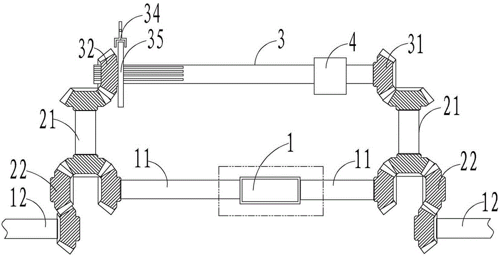
[0064] Embodiment one: if figure 1 As shown, the power output shaft 11 of the differential 1 meshes with the relay gear 22 through the gear at one end of the relay shaft 21, and the wheel shaft 12 meshes with the relay gear 22 after passing through, so that when the synchronous shaft is not working, the power is transmitted by the power The output shaft 11 is transmitted to the wheel shaft 12, and the rotation direction of the wheel shaft 12 is the same as that of the power output shaft 11; the shift fork 34 moves the shift fork piece 35 to move, so that the first interlocking gear 32 approaches the gear at the other end of the relay shaft 21 and After meshing, the two power output shafts 11 of the differential 1 are synchronized, so that the two axles 12 are also synchronized. At this time, the differential is functionally isolated, but power is still being transmitted, but the differential function is locked. ; The clutch 4 on the synchronous shaft 3 is optional and can be o...

Embodiment 2

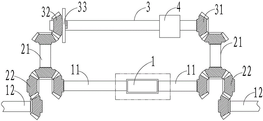
[0065] Embodiment two: if figure 2 As shown, the difference from Embodiment 1 is that the shift fork 34 and the shift fork piece 35 are replaced by a synchronizer 33, so that when the synchronizer is not working, one side of the first linkage gear 32 and the synchronizer 33 are connected to the same side. The wheel shaft 12 is synchronized, the other side of the synchronous shaft 3 and the synchronizer 33 is synchronized with the other side of the wheel shaft 12, and the synchronizer 33 is activated to link the first linkage gear 32 and the synchronous shaft 3 so as to synchronize the two wheel shafts 12. One end of the synchronizer 33 is clamped with the synchronous shaft 3, and the other end is fixedly connected with the first linkage gear 32. When the synchronization device is not started, the two ends (sides) of the synchronizer 33 rotate respectively. After the synchronizer 33 is activated, the linkage gear and the synchronization gear are locked. The shaft 3 achieves th...

Embodiment 3

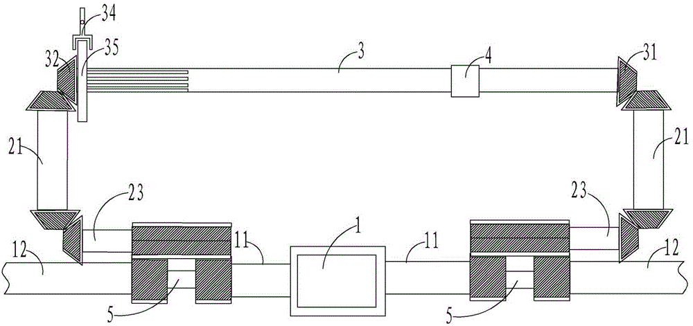
[0066] Embodiment three: as image 3 As shown, the difference from Embodiment 1 is that the wheel shaft 12 and the power output shaft 11 on the same side are meshed at one end of the same branch shaft 5, and the other end of the branch shaft 5 is connected to the second linkage gear of the synchronization device through the relay shaft 21 31 meshes with the first linkage gear 32.


PUM


Abstract

The invention relates to a differential stop device for a vehicle. The differential stop device comprises a differential mechanism, a synchronizing device enabling two power output shafts of the differential mechanism to be synchronous, a left wheel axle and a right wheel axle. The synchronizing device comprises a synchronizing shaft, a linkage mechanism inserted into one end of the synchronizing shaft, and a second linkage gear fixedly arranged at the other end of the synchronizing shaft. The left wheel axle and the right wheel axle are meshed with the two power output shafts of the differential mechanism respectively through the linkage mechanism and the second linkage gear. When one drive wheel of the vehicle gets stuck, the synchronizing device enables the left wheel axle and the right wheel axle to be synchronous, the differential function of the differential mechanism is isolated, the left wheel axle and the right wheel axle can obtain identical power and torque, and after the stuck wheel obtains the power, the vehicle can get out of the trap more easily.

Description

technical field [0001] The invention relates to a vehicle differential speed stop device. Background technique [0002] At present, many vehicles are equipped with a differential to improve the stability of the vehicle when turning. However, if one of the driving wheels of the vehicle is stuck or the vehicle is trapped, the stuck wheel will not get power, but the unstuck wheel will not get power. The wheels spin wildly, so that the vehicle cannot get out of trouble. If the differential is not installed, the vehicle will not be able to achieve the effect of power distribution when the vehicle turns or the wheels on both sides need different power. Therefore, the application of the differential will give the vehicle a stable driving. Under the situation of force adding force, also brought some problems simultaneously, can not make the limited tire of vehicle obtain enough power. Contents of the invention [0003] The purpose of the present invention is to overcome the defec...

Claims


Application Information

Patent Timeline
IPC IPC(8): F16H48/20F16H48/24
CPCF16H48/20F16H48/24
Inventor 郭英杰
Owner 郭英杰
Why Eureka
Try Eureka