Eureka AIR delivers breakthrough ideas for toughest innovation challenges, trusted by R&D personnel around the world.

Under-pressure LNG flash experimental method

An experimental method and flash evaporation technology, applied in the investigation phase/state change and other directions, can solve the problems of jet fire, shortage, and high LNG storage pressure, and achieve the effects of reducing gasification loss, automatic data collection, and accurate measurement results.

Active Publication Date: 2015-07-22
CHINA PETROLEUM & CHEM CORP QINGDAO RES INST OF SAFETY ENG +1
View PDF5 Cites 2 Cited by
  • Summary
  • Abstract
  • Description
  • Claims
  • Application Information

AI Technical Summary

Problems solved by technology

[0002] LNG filling station, due to the high storage pressure of LNG (generally, the working pressure of LNG storage tanks is 1.0MPa), when the valves and pipelines are in failure or accident state, once the LNG storage tank leaks, it will cause the pressurized LNG to leak from the leakage port. When spraying out, an LNG liquid pool will be formed on the ground when it encounters an obstacle, and the LNG absorbs the surrounding heat and quickly vaporizes. If it encounters an ignition source, a liquid pool fire or a jet fire accident may occur
[0003] At present, the research on the spread fire of LNG liquid pool mainly focuses on the related characteristics of the spread fire on the known scale of the LNG liquid pool. The scale of the liquid pool is an important parameter to accurately predict the impact of the spread fire of the LNG liquid pool; There is a lack of in-depth research on whether the LNG under free injection or hindered injection can form a liquid pool, or how large a liquid pool can be formed.
Moreover, there is no experimental method for flashing LNG under pressure in the prior art, which can provide true and credible experimental data for the scale and proportion of the liquid pool formed by the flashing of LNG under pressure

Method used


Image

  • Under-pressure LNG flash experimental method

Examples


Embodiment Construction

[0046] Below in conjunction with accompanying drawing and specific embodiment the present invention is described in further detail:

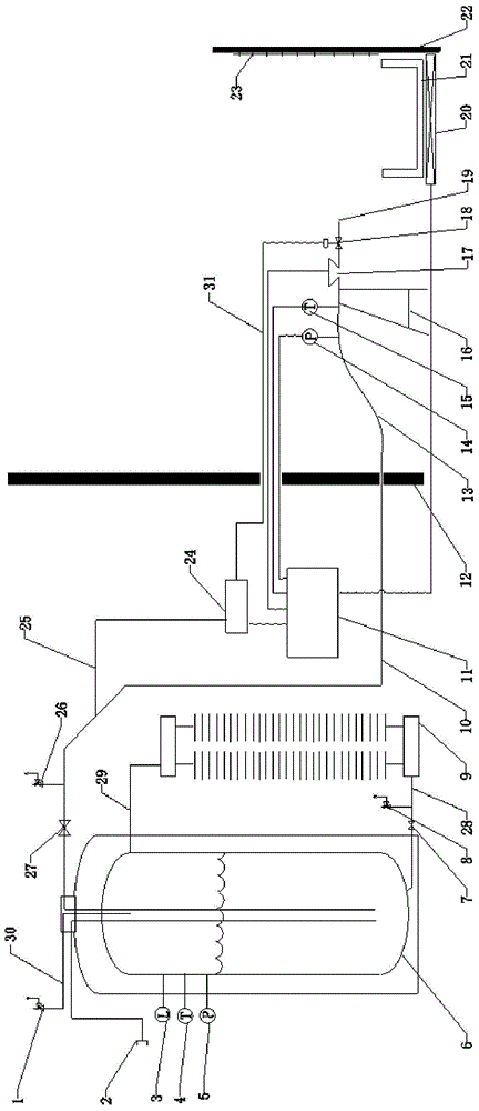
[0047] combine figure 1 As shown, the pressurized LNG flash experiment platform includes LNG storage and pressure regulating delivery device, LNG injection experiment device, measurement control device and safety protection device. in,

[0048] The LNG storage and pressure regulating delivery device is used to realize the storage of LNG, the regulation of pressure, and the delivery of LNG.

[0049] Specifically, the LNG storage pressure regulating delivery device includes an LNG storage tank 6 , a forced vaporizer 9 and a first LNG delivery pipeline 10 . The first LNG delivery pipeline 10 is made of low-temperature heat-insulating material.

[0050] An LNG storage tank filling pipeline 2 is connected to the LNG storage tank 6 for injecting LNG into the LNG storage tank. One end of the liquid filling pipeline 2 for the LNG storage tank is pro...


PUM


Abstract

The invention discloses an under-pressure LNG flash experimental method. The experimental method based on an under-pressure LNG flash experimental platform can be used for processes such as LNG pressure adjustment, LNG jet control and LNG liquid bath measurement and can be further used for conducting a research on a liquid bath scale by under-pressure LNG under free jet or hindered jet under the conditions of different jet apertures, different angles, different heights, different jet distances and the like by adjusting the jet apertures of the LNG nozzles, the bracket angles and heights, and the distances of barriers and the like according to the experimental objective. The experimental method disclosed by the invention can be used for realizing experimental remote operation and data automatic acquisition and has the characteristics of being safe and reliable and high in experimental repeatability. In addition, the method is based on an under-pressure LNG flash experimental platform, and an insulating liquid receiving disc is adopted, so that the gasifying loss of the LNG in the process of forming the liquid bath can be reduced, and therefore, the measurement result is relatively accurate.

Description

technical field [0001] The invention belongs to the technical field of pressurized liquid injection, and in particular relates to a pressurized LNG flashing experiment method. Background technique [0002] LNG filling station, due to the high storage pressure of LNG (generally, the working pressure of LNG storage tanks is 1.0MPa), when the valves and pipelines are in failure or accident state, once the LNG storage tank leaks, it will cause the pressurized LNG to leak from the leakage port. When spraying out, an LNG liquid pool will be formed on the ground when it encounters an obstacle. The LNG absorbs the surrounding heat and quickly vaporizes. If it encounters an ignition source, a liquid pool fire or a jet fire accident may occur. [0003] At present, the research on the spread fire of LNG liquid pool mainly focuses on the related characteristics of the spread fire on the known scale of the LNG liquid pool. The scale of the liquid pool is an important parameter to accurat...

Claims


Application Information

Patent Timeline
Patent Type & Authority Applications(China)
IPC IPC(8): G01N25/12
Inventor 鲍磊王全国党文义凌晓东张杰东于安峰韩中枢
Owner CHINA PETROLEUM & CHEM CORP QINGDAO RES INST OF SAFETY ENG
Why Eureka
Eureka Blog
Learn More