A lighting device with a communication function and its electricity consumption statistics method
A technology of a lighting device and a statistical method, which is applied in the field of lighting, can solve the problems of not being able to know whether the circuit is normal, and not being able to count the power consumption of the WiFi module and the light source module, so as to achieve the effect of improving convenience and accuracy
- Summary
- Abstract
- Description
- Claims
- Application Information
AI Technical Summary
Problems solved by technology
Method used
Image

Examples
Embodiment 1
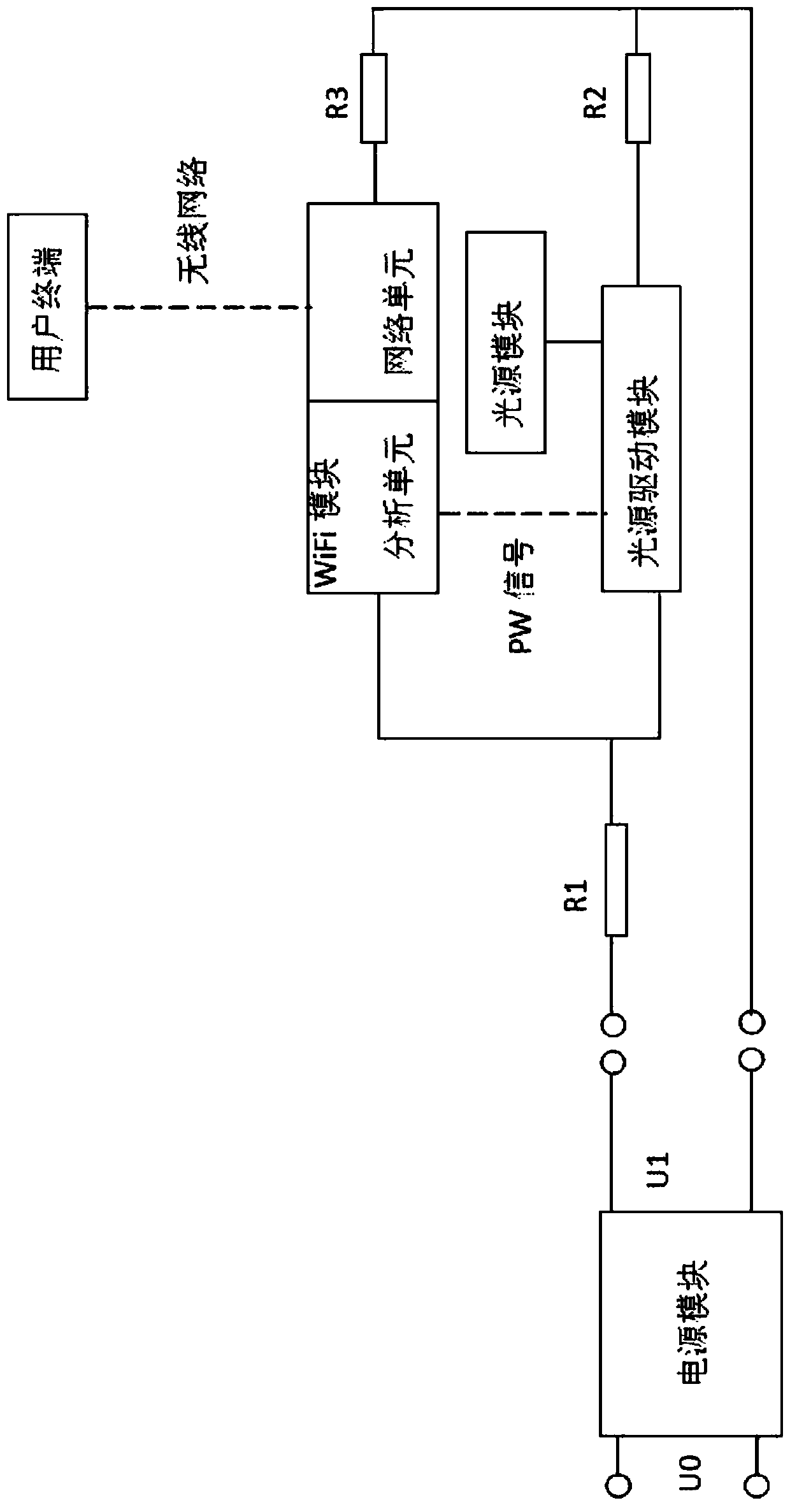
[0045] In this embodiment, the lighting device with communication function is an LED lamp, which includes a WiFi module, a light source driving module and a light source module. There is a wireless connection between the WiFi module in the LED lamp and the terminal. After receiving the instruction related to the adjustment of lighting characteristics sent by the terminal, the WiFi module sends a signal instruction to the light source driving module to drive the light source module to execute the corresponding dimming instruction. The aforementioned lighting characteristic adjustment includes but not limited to: turning on / off the light emitting unit of the light source module, adjusting light color, brightness, color temperature and set brightness, color and color temperature periodic change parameters.
[0046] Standard power data corresponding to a specific light source state is pre-stored in the WiFi module. The foregoing light source state includes: a combination of on and...
Embodiment 2
[0052] On the basis of Example 1, such as figure 1 As shown, a test resistor R1 is provided on the power supply circuit of the lighting device. At the same time, test resistors R2 and R3 are respectively set on the branches connected to the WiFi module and the light source driving module to measure the circuit current data I1, I2 and I3. Wherein, the aforementioned test resistors R1 , R2 , and R3 are all small resistors, such as 0.01 ohm and 1 ohm. In this way, the power consumption of the test resistors R1, R2, and R3 can be ignored, and it is also convenient for calculation and processing.
[0053] A timer is also provided in the WiFi module, preferably, the timer is built in the processing chip of the WiFi module. The timer is used to count the power consumption time under each working power, and store it in the WiFi module as the second working time data. In use, the output voltage U1 is determined by the input voltage U0 and the power conversion efficiency η. Output p...
Embodiment 3
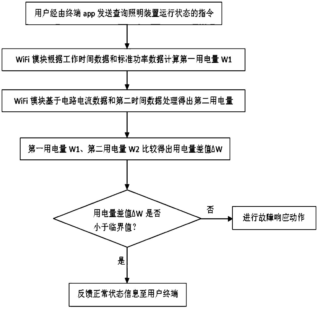
[0058]As an improvement and supplement to Embodiments 1 and 2, the user can make settings related to power consumption through the app or computer software on the terminal, including but not limited to: power consumption data feedback cycle, power consumption set value, power consumption How to interact with excess power. For example, the user selects a set value of power consumption and / or an interaction mode within a specific time period according to needs, and the setting information is sent to the WiFi module. The WiFi module compares the power consumption statistical data with the power consumption set value regularly or irregularly. When the WiFi module determines that the power consumption within the set time period exceeds the set value, the WiFi module outputs a corresponding dimming signal command to the light source driving module according to the setting information related to the interaction mode, so that the light source module performs interactive actions. At t...
PUM
 Abstract
Description
Claims
Application Information
 - R&D
- Intellectual Property
- Life Sciences
- Materials
- Tech Scout
- Unparalleled Data Quality
- Higher Quality Content
- 60% Fewer Hallucinations
Browse by: Latest US Patents, China's latest patents, Technical Efficacy Thesaurus, Application Domain, Technology Topic, Popular Technical Reports.
© 2025 PatSnap. All rights reserved.Legal|Privacy policy|Modern Slavery Act Transparency Statement|Sitemap|About US| Contact US: help@patsnap.com