Test device for measuring plates for distributors of photovoltaic header boxes

A photovoltaic combiner box and testing device technology, which is applied in the direction of measuring devices, measuring electrical variables, and electronic circuit testing, can solve the problems of low efficiency and complex structure of the testing device, and achieve the goal of improving test efficiency, improving safety, and simplifying the structure. Effect

Active Publication Date: 2015-07-22
XUJI GRP +2
View PDF7 Cites 7 Cited by
  • Summary
  • Abstract
  • Description
  • Claims
  • Application Information

AI Technical Summary

Problems solved by technology

[0007] The purpose of the present invention is to provide a test device for testing the photovoltaic combiner box m

Method used


Image

  • Test device for measuring plates for distributors of photovoltaic header boxes
  • Test device for measuring plates for distributors of photovoltaic header boxes
  • Test device for measuring plates for distributors of photovoltaic header boxes

Examples


Embodiment 1

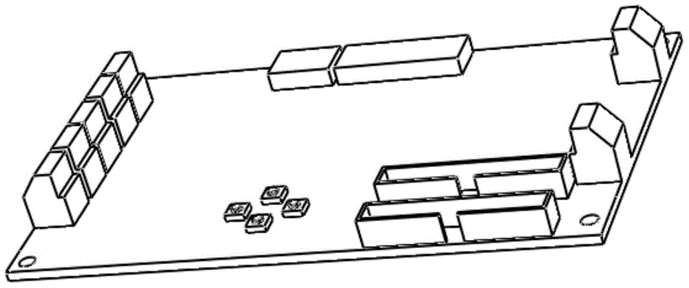
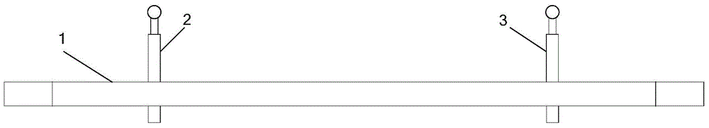
[0025] Such as figure 2 As shown, the test device of the present embodiment includes a base 1, an input test probe 2 and an output test probe 3, the input test probe and the output test probe are vertically fixed on the base, and the upper end of the input test probe is connected to the test probe to be measured. The bottom interface of the input terminal of the board is mated and inserted, the upper end of the output test probe is matched with the bottom interface of the output terminal of the board to be measured, the lower end of the input test probe and the output test probe are connected to the measurement wire, the input test probe and the output test probe The installation position of the needle matches the position of the input and output terminals of the board to be measured.

[0026] During the test, connect the interface at the bottom of the terminal of the board to be measured with the corresponding test probe, and plug the board to be measured into the test probe...

Embodiment 2

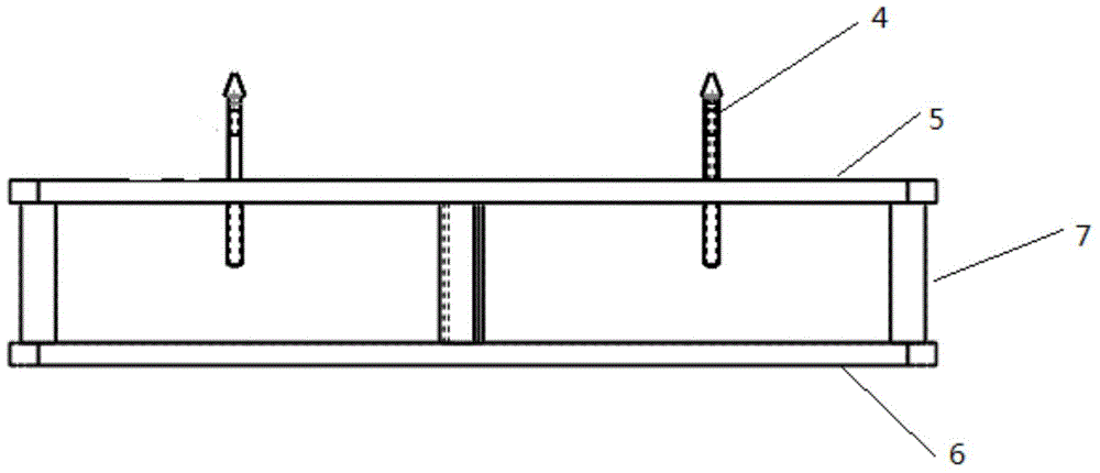
[0029] Such as image 3 As shown, this embodiment is basically the same as Embodiment 1, and the part that differs from it is: in this embodiment, a positioning probe 4 for accurately docking the measurement board is arranged on the base 1, and the installation position of the positioning probe is related to the measurement The mounting holes of the board correspond to each other, and at least two positioning probes are installed, and positioning probes are installed on both sides of the measurement board, and the number of positioning probes on both sides is not limited.

[0030] In addition, in this embodiment, the base is composed of upper and lower insulating panels 5, 6 and insulating pillars 7, and the insulating pillars are supported between the upper and lower insulating panels so that a certain gap is formed between the upper and lower insulating panels. Place the test leads connected to the test probes between the upper and lower insulation panels, so that the operat...

Embodiment 3

[0033] Such as Figure 4 As shown, this embodiment is basically the same as Embodiment 2. The difference is that the base adopts the structure of a layer of insulating panel. At this time, the test probes are inserted on the base, including the part located on the upper side of the insulating panel and the part located on the insulating panel. The part on the lower side of the panel, where the test probes are located on the lower side of the insulating panel, is connected with the measuring wires, so that the metal conductive part is located on the lower side of the plexiglass plate, which can prevent the wires from being exposed outside, thereby preventing the tester from Accidental electric shock accidents can also protect the personal safety of testers.

[0034] In addition, in this embodiment, an unlocking baffle 9 and a rack buckle 8 are arranged on the upper insulating panel of the base, and the unlocking baffle and the rack buckle here are used to fix the measuring boar...


PUM


Abstract

The invention relates to a test device for measuring plates for distributors of photovoltaic header boxes. The test device comprises a base, an input test probe and an output test probe. The input test probe and the output test probe are vertically fixed onto the base, the upper end of the input test probe is fittingly spliced with a bottom interface of an input terminal of a to-be-tested measuring plate, the upper end of the output test probe is fittingly spliced with a bottom interface of an output terminal of the to-be-tested measuring plate, and the lower end of the input test probe and the lower end of the output test probe are connected with measuring wires. According to the scheme, the test device has the advantages that the test probes are fixed onto the base and are connected with the test wires, the measuring plate can be spliced onto the test probes when about to be tested and can be tested after being powered on, accordingly, the test efficiency can be improved, the test device is simple in structure and easy to produce and apply; owing to the design of the double-layer base, the test wires can be arranged in gaps on the upper and lower surfaces of the base, the wire contact possibility can be reduced for operators, and the safety of test procedures can be improved.

Description

technical field [0001] The invention relates to a testing device for a measuring board of a shunt of a photovoltaic combiner box. Background technique [0002] The photovoltaic combiner box can connect a certain number of photovoltaic cells with the same specifications in series to form a photovoltaic series, and then connect several photovoltaic series in parallel to the combiner box. , Photovoltaic inverters, AC power distribution cabinets, etc., are used together to form a complete photovoltaic power generation system. [0003] The traditional test method of photovoltaic combiner box shunt measurement board requires a professional tester to dismantle the wiring. The dismantling work is carried out on an ordinary exposed workbench without any protective measures, and there is a risk of electric shock. Such as figure 1 As shown, the common measuring board has 9 2P terminals, and the measured wiring and disassembly time is about 5 minutes. Due to human factors, errors in t...

Claims


Application Information

Patent Timeline
IPC IPC(8): G01R31/28G01R35/00
Inventor 王萌胡明会王献奎杨晓光李延青张聪
Owner XUJI GRP
Why Eureka
Try Eureka