
Distribution automation monitor terminal

A distribution automation and monitoring terminal technology, applied in the substation/distribution device housing, electrical components, circuit devices, etc., can solve the problems of inability to achieve real-time and uninterrupted monitoring, high waterproof requirements, lack of water, etc., to achieve continuous Uninterrupted battery life, improved market competitiveness, and compact internal wiring

Inactive Publication Date: 2015-07-22
江苏汉天星配电自动化科技有限公司
View PDF3 Cites 5 Cited by
  • Summary
  • Abstract
  • Description
  • Claims
  • Application Information

AI Technical Summary

Problems solved by technology

[0003] However, conventional distribution automation monitoring terminals, such as "a distribution network automation monitoring terminal device" disclosed in Chinese patent 201410387039.3, "a distribution network automation terminal monitoring device and monitoring system" disclosed in Chinese patent 201410481621.6, Chinese patent 201210518788.6 discloses "A Distributed Distribution Network Automation Monitoring Terminal". Since these distribution automation monitoring terminals are installed outdoors all year round, they have high requirements for waterproofing. , the above distribution automation monitoring terminals all lack corresponding waterproof and heat dissipation functions; at the same time, these conventional distribution automation monitoring terminals lack corresponding power storage modules. When there is a problem with the external power supply line, they can only be shut down passively, so they cannot Real-time uninterrupted monitoring; moreover, the conventional power distribution automation monitoring terminal adopts an integral fixed installation structure, which is very inconvenient when some functional modules need to be added or deleted, which seriously affects its expansion performance

Method used


Image

  • Distribution automation monitor terminal
  • Distribution automation monitor terminal
  • Distribution automation monitor terminal

Examples


Embodiment Construction

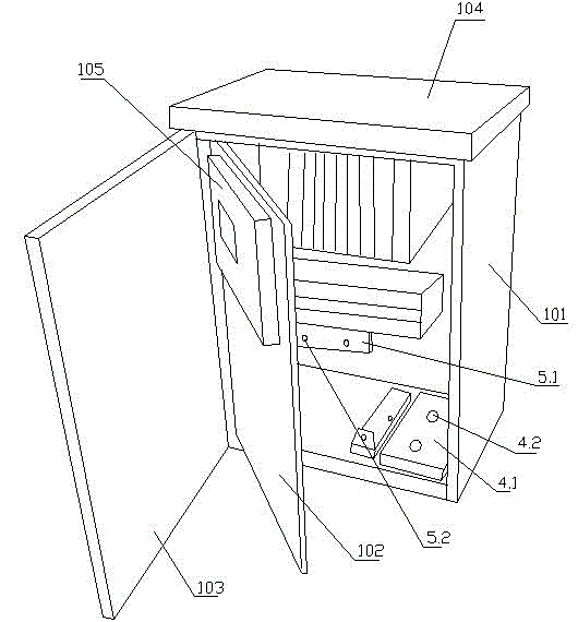
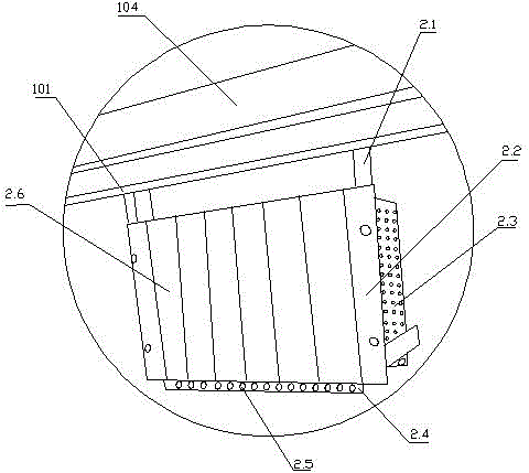
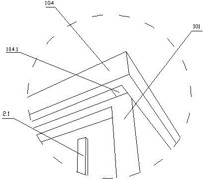
[0031] see Figure 1~8 , a power distribution automation monitoring terminal related to the present invention, the terminal includes a box body 101, the box door of the box body 101 is provided with double doors of an inner box door 102 and an outer box door 103, and the inner box door 102 A display device 105 is installed on it, so that the outdoor dustproof and waterproof performance of the monitoring terminal can be increased through the structural design of the double box door inside and outside; at the same time, a shutter 104 is arranged on the top of the box body 101, and a housing is arranged at the bottom of the shutter 104. The groove of the box body 101, and the left and right sides of the groove are provided with step plates 104.1, the top of the box body 101 is connected to the step plate 104.1, and the waterproof and dustproof performance of the box body 101 is further increased by using the shutter 104 , and there is a certain gap between the top of the box body...


PUM


Abstract

The invention relates to a distribution automation monitor terminal comprising a box (101). A door of the box (101) comprises an inner door (102) and an outer door (103); the inner door (102) is provided with a display device (105); the top of the box (101) is provided with a shade (104); the bottom of the shade (104) is provided with a recess for holding the box (101); the left and right sides of the recess are provided with step plates (104.1); the top of the box (101) is connected to the step plates (104.1); a battery, a plurality of function modules and a wiring terminal mounted on a slide rail are mounted within the box (101). The distribution automation monitor terminal is in modular installation, has good extensibility, is good in waterproofing and radiating performances and is available for continuous operation.

Description

technical field [0001] The invention relates to a distribution automation monitoring terminal. Background technique [0002] At present, with the industrialization of electric power, users have higher and higher requirements for power supply quality and reliability, which requires the power sector to provide safe, economical and reliable power. Power distribution automation is the use of modern electronic automation, computers, communications and Network technology, information integration of online and offline data of the power grid, distribution network data and user data, power grid structure and geographic graphics, etc., to realize modern power distribution management such as monitoring, protection, and control of power distribution equipment in normal operation and in an accident state ; [0003] However, conventional distribution automation monitoring terminals, such as "a distribution network automation monitoring terminal device" disclosed in Chinese patent 2014103...

Claims


Application Information

Patent Timeline
IPC IPC(8): H02B15/00H02B1/56H02B1/28H02J13/00
Inventor 高正洪
Owner 江苏汉天星配电自动化科技有限公司
Learn More