Eureka AIR delivers breakthrough ideas for toughest innovation challenges, trusted by R&D personnel around the world.

Rectifying circuit and rectifying method thereof

A rectification circuit and voltage technology, applied in the field of active Ethernet, can solve problems such as poor heat dissipation, high power consumption of the solution, and overheating of the product, and achieve low power consumption, reduced power consumption, heat, and low cost

Active Publication Date: 2015-07-22
北京中航融智科技有限公司
View PDF6 Cites 1 Cited by
  • Summary
  • Abstract
  • Description
  • Claims
  • Application Information

AI Technical Summary

Problems solved by technology

[0003] At present, in practical applications, the rectifier bridge is usually placed in the clearance area of ​​the PCB, and the heat dissipation is poor, which will cause overheating problems to the entire product
In the application of POE PD, the diode rectifier bridge is basically used, the voltage drop is fixed, the power consumption of the solution is large, and the thermal problem is serious, which makes it more and more unsuitable for the application of high-power POE

Method used


Image

  • Rectifying circuit and rectifying method thereof
  • Rectifying circuit and rectifying method thereof
  • Rectifying circuit and rectifying method thereof

Examples


Embodiment Construction

[0030] The specific embodiments of the present invention will be further described below with reference to the accompanying drawings.

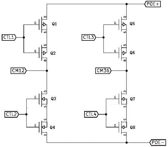
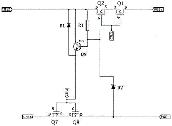
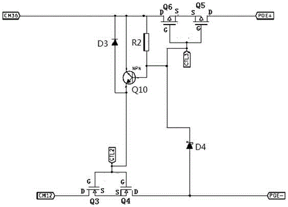
[0031] like figure 1 As shown, it is an embodiment of a rectifier circuit suitable for an active Ethernet power receiving end device. The rectifier circuit includes a first bridge arm, a second bridge arm, a third bridge arm and a fourth bridge arm which are sequentially connected to form a loop.

[0032] The first bridge arm and the second bridge arm are connected to the first input end CM12 of the rectifier circuit, the third bridge arm and the fourth bridge arm are connected to the second input end CM36 of the rectifier circuit, and the first bridge arm and the third bridge arm are connected to the second input end CM36 of the rectifier circuit. The arms are connected to the first output end POE+ of the rectifier circuit, and the second bridge arm and the fourth bridge arm are connected to the second output end POE- of the rectifier circui...


PUM


Abstract

The invention discloses a rectifying circuit. The rectifying circuit comprises a first bridge arm, a second bridge arm, a fourth bridge arm and a third bridge arm, which are orderly connected into a loop; the first input end of the rectifying circuit is connected between the first bridge arm and the second bridge arm, the second input end of the rectifying circuit is connected between the third bridge arm and the fourth bridge arm, the first output end of the rectifying circuit is connected between the first bridge arm and the third bridge arm, and the second output end of the rectifying circuit is connected between the second bridge arm and the fourth bridge arm; each of the first bridge arm, the second bridge arm, the third bridge arm and the fourth bridge arm is provided with an MOS tube. According to the rectifying circuit, the MOS is rectified and applied to the equipment side at the receiving end; besides, in combination with a related control circuit, the rectification of the equipment side at the receiving end of the active Ethernet is realized, and the power consumption and the heat of the whole system are reduced, and consequently, the cost is lower than that of the controller scheme of the prior art, while the power consumption is lower than that of the rectifier scheme of the prior art.

Description

technical field [0001] The invention relates to the technical field of active Ethernet, in particular to a rectification circuit and a rectification method applied to a power receiving end device of an active Ethernet. Background technique [0002] In the application of the Power Over Ethernet (POE) receiving end device (Powered Device, PD), in order to adapt to different power supply equipment (Power Sourcing Equipment, PSE), a rectifier bridge will be added at the input end to Rectify the direction-indeterminate DC power supply to the direction-determined direct current. The forward voltage drop of the existing silicon rectifier bridge will reach 0.9~1.5V; in the POE AT protocol, the current flowing through the rectifier bridge will reach more than 700mA, so the power loss on the rectifier bridge will reach 0.6~1W, and In the future higher specification agreement, the power of POE will reach 60W~150W, the current flowing through the rectifier bridge will reach 2-4A, and t...

Claims


Application Information

Patent Timeline
IPC IPC(8): H02M7/217
Inventor 沈云峰李业旺
Owner 北京中航融智科技有限公司
Why Eureka
Eureka Blog
Learn More