
Relay driving circuit and low-power method for relays

A technology for driving circuits and relays, applied in relays, circuits, electrical components, etc., can solve problems such as increased power consumption of relays

Inactive Publication Date: 2019-10-25
东莞市鑫鼎元科技有限公司
View PDF3 Cites 2 Cited by
  • Summary
  • Abstract
  • Description
  • Claims
  • Application Information

AI Technical Summary

Problems solved by technology

However, the traditional relay control circuit always applies the rated voltage, and the power consumption of the relay is greatly increased.

Method used


Image

  • Relay driving circuit and low-power method for relays
  • Relay driving circuit and low-power method for relays
  • Relay driving circuit and low-power method for relays

Examples


Embodiment Construction

[0037] The following will clearly and completely describe the technical solutions in the embodiments of the present invention with reference to the accompanying drawings in the embodiments of the present invention. Obviously, the described embodiments are only some, not all, embodiments of the present invention. Based on the embodiments of the present invention, all other embodiments obtained by persons of ordinary skill in the art without making creative efforts belong to the protection scope of the present invention.

[0038] The terms "comprising" and "having" and any variations thereof in the specification and claims of the present invention and the above drawings are intended to cover non-exclusive inclusion, and the terms "first" and "second" are only used for distinguishing names , does not represent the size or ordering of numbers. For example, a process, method, system, product or device comprising a series of steps or units is not limited to the listed steps or units...


PUM


Abstract

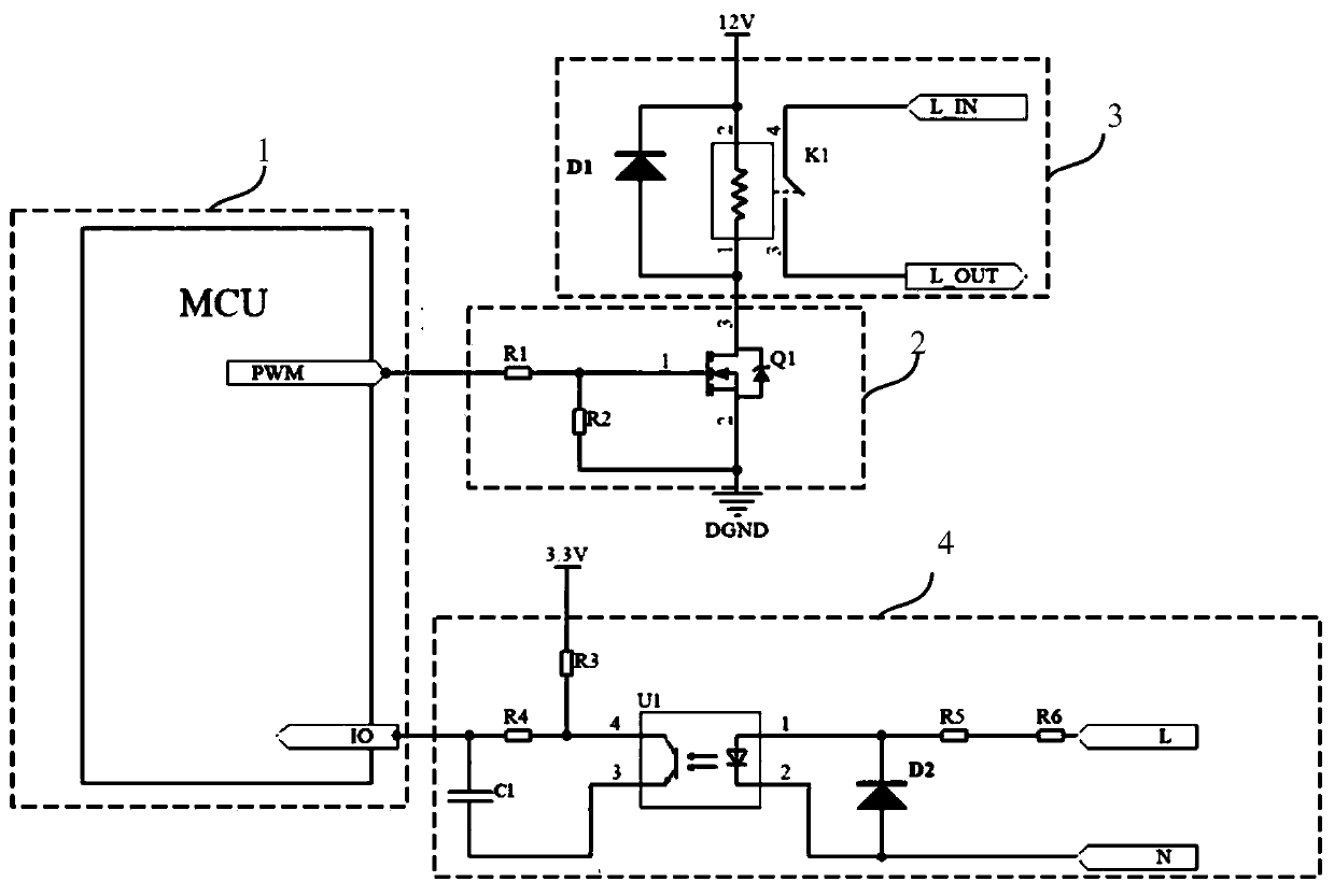
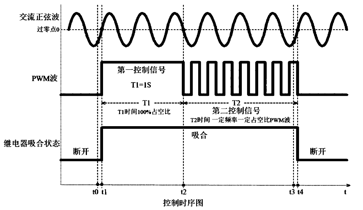
The invention discloses a relay driving circuit and a low-power method for relays. The circuit includes a microcontroller, a PWM driver, a relay and a zero crossing point detector. The method for protecting a relay by using the circuit includes the following steps: detecting whether there is a switching demand for the relay currently; and when detecting that there is a switching demand, controlling the switching time based on a zero crossing signal detected by the zero crossing point detector, and making the PWM driver drive an MOS tube to control the switching of the relay. By employing the method of the invention, the sustaining voltage of a relay can be reduced without other circuit adding means, and the circuit cost can be saved. Moreover, the power consumption of the relay can be reduced, the heat generation can be reduced, the service life of the relay can be greatly increased, and the effect of heat generation on other electronic components can be reduced.

Description

technical field [0001] The invention relates to the technical field of relay protection, in particular to a relay driving circuit and a method for low power consumption of the relay. Background technique [0002] The heating of the power relay in the equipment circuit is mainly composed of two parts, one is the heating caused by the excessive power consumption of the coil; the other is the heating caused by the excessive contact resistance when the relay contacts are turned on. The contact resistance of the contact can be achieved by increasing the size of the contact to achieve the smallest possible contact resistance to improve the loss and heat caused by the contact resistance. The existing relay control circuit is to apply a rated voltage to the relay coil, and the relay will pull in and work, and the coil resistance will generate heat. In fact, after the relay pulls in and works, only a small voltage relative to the rated voltage is required to maintain the pull-in stat...

Claims


Application Information

Patent Timeline
IPC IPC(8): H01H47/02
CPCH01H47/02
Inventor 何皇芝龚伟龙郭瑞李现峰林伟强
Owner 东莞市鑫鼎元科技有限公司
Learn More