Die-casting die capable of secondarily laterally pulling core

A die-casting mold and lateral core-pulling technology, which is applied in the field of molds, can solve problems such as product packaging mold, bending deformation, product bending deformation, etc., and achieve the effect of improving production efficiency

Active Publication Date: 2015-07-29
NINGBO BEILUN HUASHENG MOLD FACTORY
View PDF6 Cites 9 Cited by
  • Summary
  • Abstract
  • Description
  • Claims
  • Application Information

AI Technical Summary

Problems solved by technology

[0003] One purpose of the present invention is to solve the problem that the existing aluminum alloy die-casting molds are difficult to simultaneously form the lateral forming hole and the radial blind hole on the inner wall of the lateral forming hole, and provide a method that can realize secondary lateral core pulling The die-casting mold can simultaneously form the lateral forming hole and the radial blind hole on the inner wall of the lateral forming hole at one time, thereby avoiding subsequent secondary machining and improving production efficiency
[0004] Another object of the present invention is to solve the problem that the existing aluminum alloy die-casting mold is prone to product package upper mold and bending deformation when forming products with openings on both sides of the upper and lower sides, and to provide a method that can ensure that all products stay on the bottom during molding. The die-casting mold of the mold can effectively avoid the bending deformation of the formed product

Method used


Image

  • Die-casting die capable of secondarily laterally pulling core
  • Die-casting die capable of secondarily laterally pulling core
  • Die-casting die capable of secondarily laterally pulling core

Examples


Embodiment Construction

[0022] The present invention will be further described below in conjunction with the accompanying drawings and specific embodiments.

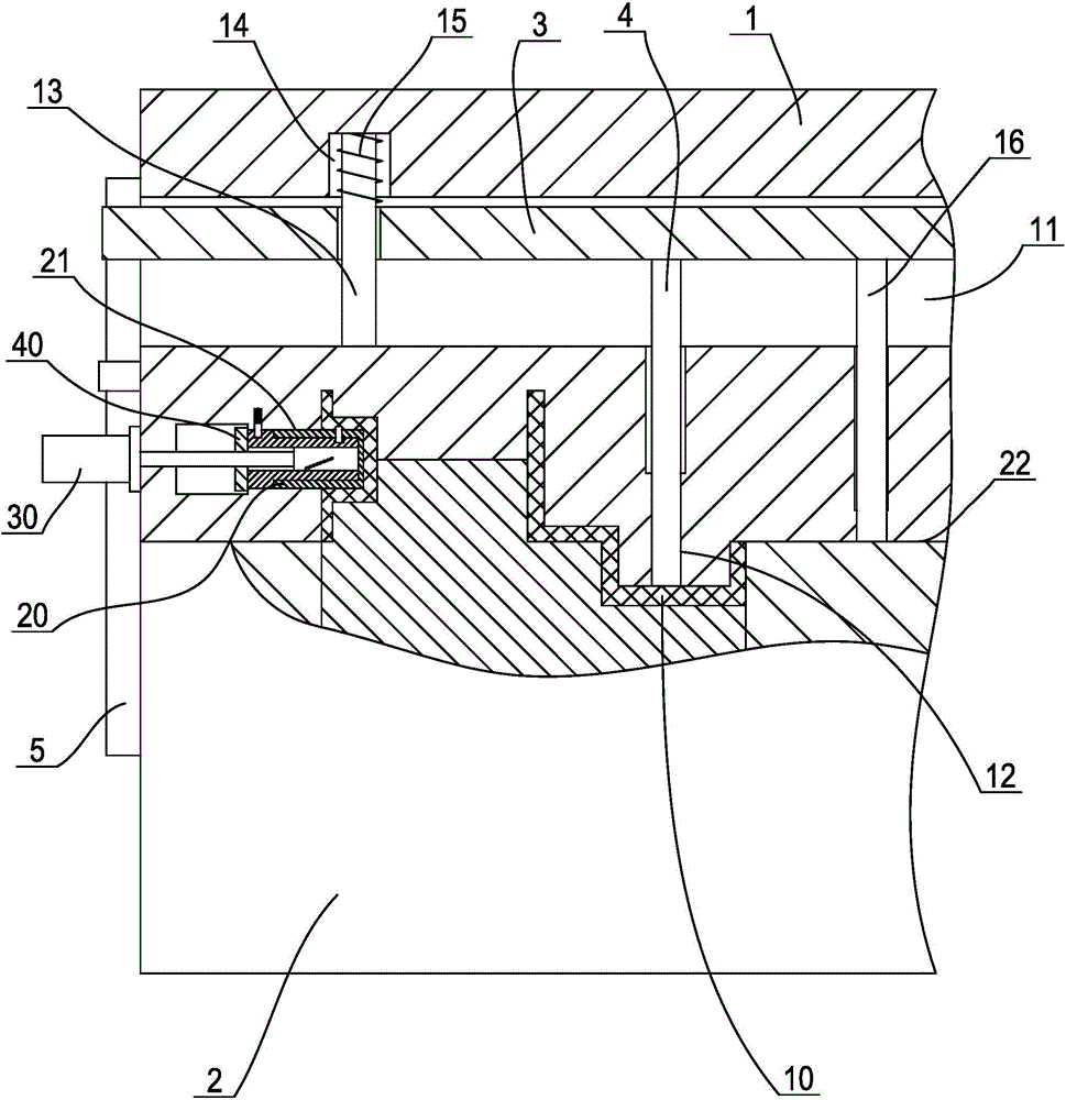
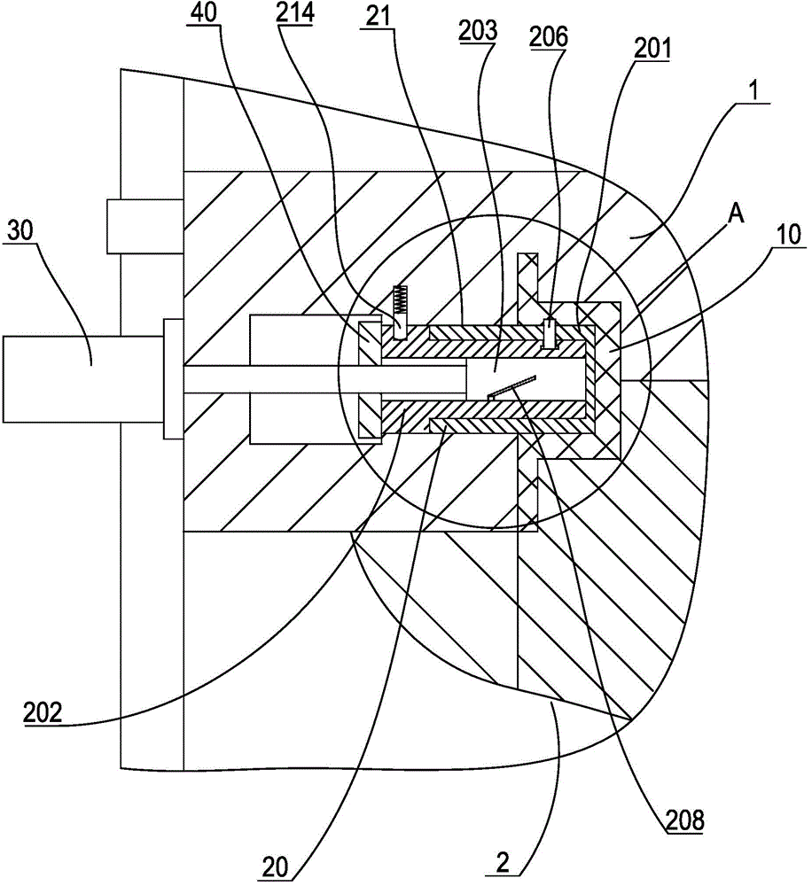
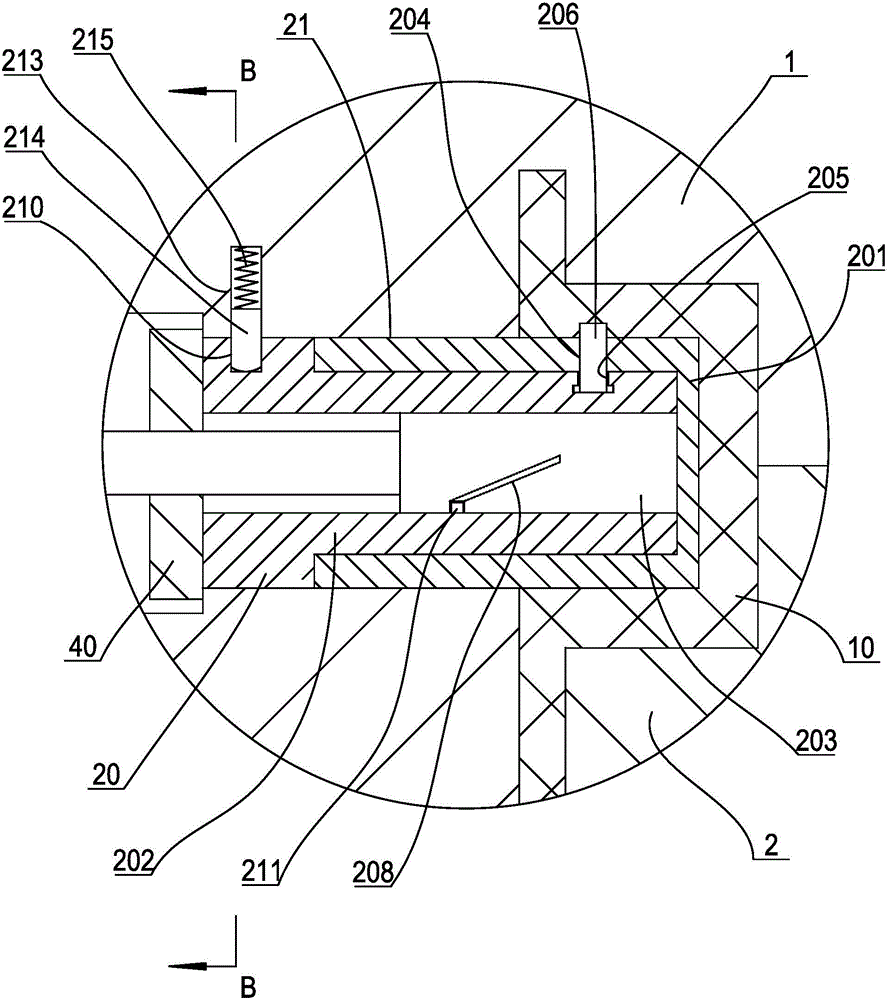
[0023] Such as figure 1 As shown, a die-casting mold capable of secondary lateral core pulling is suitable for forming products with lateral holes and radial blind holes in the lateral holes; at the same time, it can also be formed with Products with openings or concave cavities, or products with close molding forces on the upper and lower sides of the parting surface. It specifically includes an upper mold 1 with a pouring system, and a lower mold 2 with an ejection mechanism. The upper mold has a lateral core-pulling hole 21, and a hole for forming a lateral hole and a radial blind hole is arranged in the lateral core-pulling hole. The main core 20 is connected with a driving cylinder 30 . For the sake of explanation, we refer to the mold splitting and mold closing directions of the upper and lower molds as the longitudinal direction of the...


PUM


Abstract

The invention discloses a die-casting die capable of secondarily laterally pulling a core. The die-casting die comprises an upper die and a lower die; a main mold core is arranged into a lateral core pulling hole in the upper die, comprising a rotating sleeve, a driving pulling core adapted into the rotating sleeve, and a mold core sleeve, wherein the mold core sleeve is in rotating connection to the small front end of the rotating sleeve; a secondary mould core is arranged at the front part of the mold core; a T-shaped clamping groove of which the depth is gradually increased in the circumferential direction is formed in the rotating sleeve; the lower end of the secondary mould core is clamped into the T-shaped clamping groove; the rear end of a driving pulling core is connected with a driving oil cylinder; a spiral groove is formed in the front part of the driving pulling core; a sliding pin which extends into the rear end of the spiral groove is arranged at the inner sidewall of the rotating sleeve; an arc-shaped groove of which the depth is gradually reduced in the circumferential direction is formed in the outer side surface of the rear end of the rotating sleeve; a spring bolt is arranged in the lateral core pulling hole; a spring bolt pressing spring is arranged at the rear end of the spring bolt. With the adoption of the die, a lateral forming hole and a radial blind hole in the inner wall of the lateral forming hole can be synchronously formed at a time, so that later secondary mechanical processing can be avoided, and the production efficiency can be increased.

Description

technical field [0001] The invention relates to the technical field of molds, in particular to a core-pulling structure of an aluminum alloy die-casting mold. Background technique [0002] Existing aluminum alloy die-casting molds usually include an upper mold, a lower mold, a pouring system arranged on the upper mold, an ejection mechanism arranged on the lower mold, and a cooling system, etc. As far as the product with cavity is concerned, in order to facilitate the ejection of the product after molding, a concave cavity is usually set on the upper mold, and a convex core is set on the lower mold. When the upper and lower molds are combined, the upper mold The cavity of the molded product is formed between the cavity body and the core of the lower mold. After the product is formed and cooled, the upper and lower molds are separated, and the product stays on the lower mold by the mold core force generated by its cooling shrinkage. Finally, the product is pushed along the m...

Claims


Application Information

Patent Timeline
Patent Type & Authority Applications(China)
IPC IPC(8): B22D17/22
Inventor 陆卫国
Owner NINGBO BEILUN HUASHENG MOLD FACTORY
Why Eureka
Try Eureka