Eureka AIR delivers breakthrough ideas for toughest innovation challenges, trusted by R&D personnel around the world.

Automated manual screwdriver, accommodation seat of automated manual screwdriver and charging circuit

A screwdriver and receiving seat technology, which is applied to screwdrivers, wrenches, wrenches, etc., can solve the problems of large outer diameter of one-way valve, inconvenient carrying, loss of bit, etc.

Active Publication Date: 2015-07-29
苏州小易科技有限公司
View PDF14 Cites 11 Cited by
  • Summary
  • Abstract
  • Description
  • Claims
  • Application Information

AI Technical Summary

Problems solved by technology

Electric screwdrivers, as the name implies, use electric motors instead of human hands to install and remove screws. Conventional small electric screwdrivers generally cannot be used manually when there is no electricity. When using manually, the output shaft of the screwdriver is active and non-locked. state
[0003] The prior art also involves some manual screwdrivers, which generally use a one-way valve to limit the position to realize the function of manual integration, but the large outer diameter of the one-way valve leads to its bulky volume, which makes the overall volume of the screwdriver product less The outer diameter is also large, which is inconvenient to carry and store
[0004] In addition, the combined screwdriver is inconvenient to carry due to the replacement of many bits, and the problem of bit loss is prone to occur. However, the storage containers of the combined screwdriver in the prior art are large in size and the internal structure is not compact. Scattering and abnormal noises often occur. For electric screwdrivers, you need to carry charging equipment or batteries, which is not easy to carry

Method used


Image

  • Automated manual screwdriver, accommodation seat of automated manual screwdriver and charging circuit
  • Automated manual screwdriver, accommodation seat of automated manual screwdriver and charging circuit
  • Automated manual screwdriver, accommodation seat of automated manual screwdriver and charging circuit

Examples


Embodiment Construction

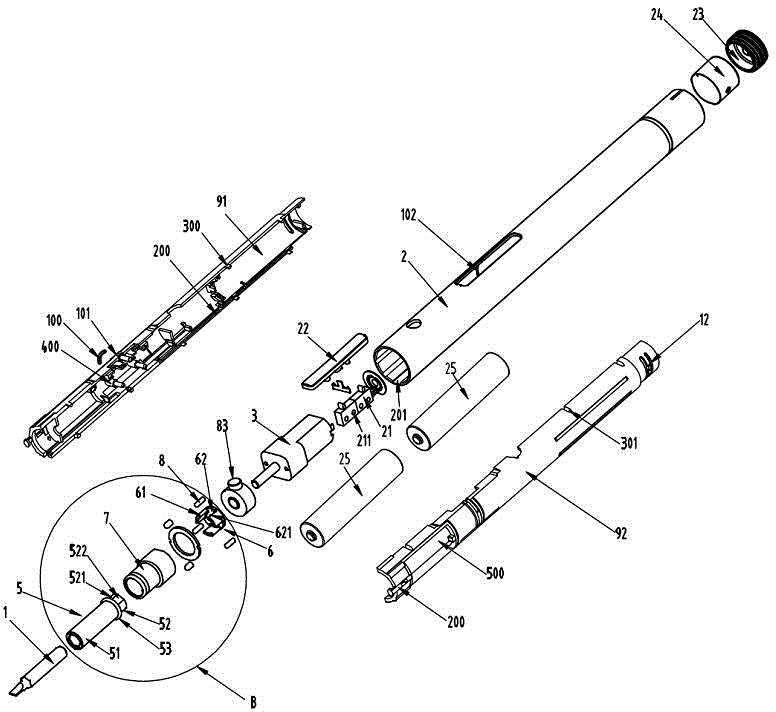
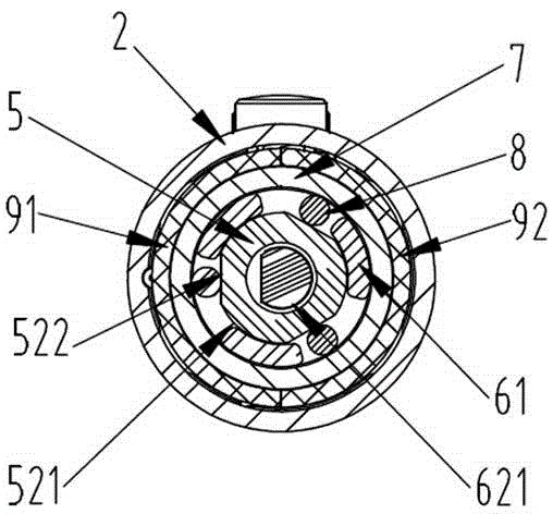
[0086] The invention provides a manual screwdriver, such as Figure 1 to Figure 5 As shown in the first embodiment shown, it includes a housing and a screwdriver bit 1 arranged in front of the housing, and a motor 3 is provided in the housing, and the motor is a geared motor. A composite mechanism 4 is provided between the screwdriver head 1 and the motor 3, and the composite mechanism enables the manual screwdriver to have a manual mode and an electric mode that can be switched between each other. Specifically, the composite mechanism 4 includes: an output shaft 5 , a support frame 6 , a bearing seat 7 , and a pin 8 .

[0087] The output shaft 5 is arranged between the screwdriver bit 1 and the motor 3. The output shaft 5 is provided with a front end 51 and a rear end 52. A fixed internal hexagon, the rear end 52 is inserted into the motor shaft of the motor 3 , and a protruding ring 53 is provided between the front end 51 and the rear end 52 . The outer profile of the cross ...


PUM


Abstract

The invention discloses a manual-automatic screwdriver which comprises a screwdriver head and a shell. A motor is arranged in the shell, and the screwdriver head is located in front of the shell. The screwdriver is characterized in that a composite mechanism is disposed between the screwdriver head and the motor and comprises an output shaft, a supporting frame, a bearing base and multiple pins, and by means of the composite mechanism, the manual-automatic screwdriver has a manual mode and an automatic mode which can be switched. By means of the screwdriver, the manual mode and the automatic mode are integrated through a transmission unit. When the screwdriver has no supplementary power supply, the screwdriver can still be normally used in the manual mode. The transmission unit takes the place of a traditional one-way valve, so that the size and the outer diameter of the screwdriver are reduced, and the screwdriver is convenient to carry and store. A tail cap is provided with a functional slot and a tail LED lamp, the functional slot can be used for charging electronic products and the tail LED lamp has a work indication function.

Description

technical field [0001] The invention relates to a screwdriver and its receiving seat, in particular to a manual and automatic screwdriver and its receiving seat, belonging to the technical field of household or professional tools. Background technique [0002] A screwdriver is a tool used to twist a screw to force it into place. Generally, screwdrivers are divided into ordinary screwdrivers, combined screwdrivers and electric screwdrivers, and electric screwdrivers are generally combined screwdrivers. Electric screwdrivers, as the name implies, use electric motors instead of human hands to install and remove screws. Conventional small electric screwdrivers generally cannot be used manually when there is no electricity. When using manually, the output shaft of the screwdriver is active and non-locked. state. [0003] The prior art also involves some manual screwdrivers, which generally use a one-way valve to limit the position to realize the function of manual integration, b...

Claims


Application Information

Patent Timeline
Patent Type & Authority Applications(China)
IPC IPC(8): B25B21/00B25B23/00B25B23/18
CPCB25B15/02B25B21/00B25B23/00B25B23/18B25F5/02
Inventor 不公告发明人
Owner 苏州小易科技有限公司
Why Eureka
Eureka Blog
Learn More