Novel anti-rolling torsion-bar system and positioning and mounting method thereof

An anti-roll torsion bar and system installation technology, which is applied in the direction of the device for lateral relative movement between the underframe and the bogie, can solve the problems of small application range, inaccurate positioning, and slow arc start

Active Publication Date: 2015-07-29
ZHUZHOU TIMES NEW MATERIALS TECH
View PDF7 Cites 8 Cited by
  • Summary
  • Abstract
  • Description
  • Claims
  • Application Information

AI Technical Summary

Problems solved by technology

The disadvantages of this positioning method are: (1) Adding a hard stop structure between the support seat assembly and the torsion arm will increase the production difficulty of the support seat, torsion arm and torsion bar shaft, and increase the production cost; if the torsion bar If positioning steps are added to the shaft, the local stress will be concentrated here. If the design is improper, it will most likely become an early failure point; (2) The lateral clearance caused by the cumulative tolerance of the roll torsion bar system installed between the frame and the car body cannot be eliminated , so that the torsion bar assembly and the support seat assembly cannot be positioned accurately
(3) When the size of the torsion bar assembly is large, a hard stop structure or a positioning piece process is complicated between the torsion bar assembly and the support seat assembly, and the processing is difficult
The disadvantages of this positioning method are: (1) The elastic stop needs to be fixed by bolts or pins, which is troublesome to install and disassemble, and there are relatively many fault points
(2) The scope of application is small, and it is not applicable when the distance between the torsion arm and the support seat is large
The disadvantages of this positioning method are: (1) It is mainly suitable for the integrally formed torsion bar, and the applicable range is small; (2) The arc of the integral torsion bar is generally large, and the arc starts slowly, which causes the supporting ball joint to be incompatible with the whole The arc of the type bending torsion bar cannot be accurately positioned, and the reliability is low
[0008] To sum up, in the prior art, in order to limit the relative movement between the torsion bar assembly and the support seat assembly and prevent the torsion bar assembly from moving laterally relative to the support seat assembly, the technical problems of the positioning method used are that the resistance to resistance cannot be eliminated. The accumulative tolerance between the installation frame of the roll torsion bar system and the car body causes a gap in the positioning of the support assembly and the torsion bar assembly, making precise positioning impossible. Relative movement causes impact and noise. For example, reducing the cumulative tolerance after assembly by improving the dimensional accuracy of the car body, frame and anti-roll torsion bar system will lead to a substantial increase in vehicle manufacturing costs; the second is that the scope of application is small , there are relatively large restrictions on the size range of the torsion bar assembly and the structure type of the torsion bar

Method used


Image

  • Novel anti-rolling torsion-bar system and positioning and mounting method thereof
  • Novel anti-rolling torsion-bar system and positioning and mounting method thereof
  • Novel anti-rolling torsion-bar system and positioning and mounting method thereof

Examples


Embodiment Construction

[0037] Embodiments of the present invention will be described in detail below in conjunction with the accompanying drawings.

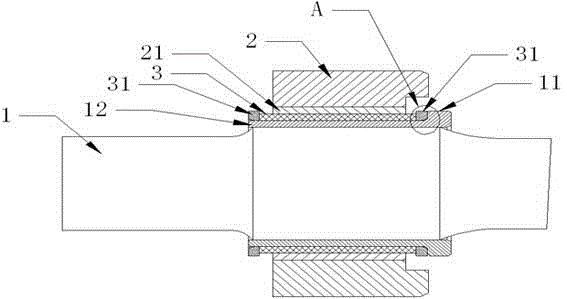
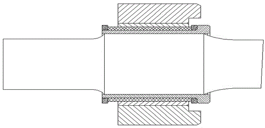
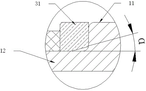
[0038] like Figure 1 to Figure 3 As shown, the new anti-rolling torsion bar system includes the torsion bar 1 and the spherical hinge support 2. The inner surface of the spherical hinge support 2 is equipped with a friction sleeve 3 through an interference connection, and the friction sleeve 3 is sleeved on the torsion bar 1 through a clearance fit. The torsion bar 1 has a limit stop 11 that limits the lateral movement of the friction sleeve 3. The friction sleeve 3 protrudes from the ball hinge support 2 and the length of the friction sleeve 3 protruding from the end surface of the ball hinge support 2 is longer than the new anti-rolling torsion bar. The cumulative tolerance between the system installed on the vehicle body and the frame, the interference force between the friction sleeve 3 and the ball joint support 2 is greater than the lateral move...


PUM


Abstract

The invention discloses a novel anti-rolling torsion-bar system. The novel anti-rolling torsion-bar system is characterized by comprising a torsion bar and a spherical hinge support, wherein a friction sleeve is connected to the internal surface of the spherical hinge support in an interference fit manner, the friction sleeve sleeves the torsion bar in a clearance fit manner, a limit block which limits the transverse movement of the friction sleeve is arranged on the torsion bar, the friction sleeve extends out of the spherical hinge support, the length, extending out of the end surface of the spherical hinge support, of the friction sleeve is larger than the accumulated tolerance of the novel anti-rolling torsion-bar system mounted between a vehicle body and a frame, and the interference force between the friction sleeve and the spherical hinge support is greater than the transverse movement force of the spherical hinge support when a vehicle runs. The novel anti-rolling torsion-bar system provided by the invention is wide in application range; when the novel anti-rolling torsion-bar system is mounted between the vehicle body and the frame, the transverse positioning is accurate, and the manufacturing cost of the vehicle does not need to be increased. The invention further provides a positioning and mounting method of the novel anti-rolling torsion-bar system.

Description

technical field [0001] The invention relates to a safety component installed between a rail vehicle body and a frame, in particular to a novel anti-rolling torsion bar system, which is used to suppress the rolling vibration of the vehicle and improve the lateral stability of the vehicle. The invention also relates to a method for positioning and installing the novel anti-rolling torsion bar system between the car body and the frame. Background technique [0002] The existing anti-roll torsion bar system for rail transit generally includes three parts: torsion bar assembly, connecting rod assembly and support seat assembly. The torsion bar assembly is fixed on the frame through the support seat assembly, and fixed on the vehicle body through the connecting rod assembly. When a roll occurs between the vehicle body and the frame, the torsion bar assembly prevents the increase of the roll angle of the vehicle body relative to the frame, thereby suppressing the roll of the vehi...

Claims


Application Information

Patent Timeline
Patent Type & Authority Applications(China)
IPC IPC(8): B61F5/24
CPCB61F5/24
Inventor 罗燕刘文松陈天鸥杜方孟邹敏佳吕士勇郭红锋
Owner ZHUZHOU TIMES NEW MATERIALS TECH
Why Eureka
Try Eureka