Aided flowing device of storage silo

A technology of storage bin and micro-orifice plate is applied in the field of flow-assisting device of storage bin, which can solve the problems of poor fluidity of powder materials, inconvenient use, and large occupied area, so as to avoid accumulation, uniform fluidization, and eliminate the The effect of stirring dead ends

Inactive Publication Date: 2015-07-29
SHANGHAI JUZONG IND
View PDF6 Cites 1 Cited by
  • Summary
  • Abstract
  • Description
  • Claims
  • Application Information

AI Technical Summary

Problems solved by technology

[0003] The Chinese patent with the application number 201220289507.x discloses a powder flow-aiding device, which includes a central shaft that is rotatably installed inside the silo, and a number of spines extending radially along the central shaft are arranged on the central shaft. One end of the shaft passes through the side wall of the silo and is connected with a power device. Although this kind of flow aid device can solve the problem of arched holes formed in the storage bin due to the poor fluidity of powder materials, the structure of this kind of flow aid device It is relatively complicated, and it occupies a large area, which is inconvenient to use

Method used


Image

  • Aided flowing device of storage silo

Examples


Embodiment

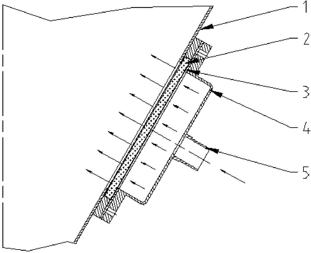
[0018] A flow-aid device for a storage bin, installed on the side of the storage bin 1 and communicated with the storage bin 1, its structure is as follows figure 1 As shown, the flow aid device includes a microporous plate 2 , a compression washer 3 , an inflatable frame 4 and a trachea connector 5 .

[0019] The side of the storage bin 1 is provided with an opening at the fitting position of the microporous plate 2, the microporous plate 2 is connected with the storage bin 1 through the opening, the microporous plate 2 is fixed by the compression gasket 3, and the inflatable frame 4 is erected On the outer surface of the microporous plate 2 and fixed by the compression gasket 3 , the outer surface of the inflatable frame 4 is connected with a trachea joint 5 .

[0020] Open a hole on the storage bin 1 and weld the flange side, put the microporous plate 2 into the flange side of the storage bin 1, add a compression gasket 3 and an inflatable frame 4, and fix the inflatable fr...


PUM


Abstract

The invention relates to an aided flowing device of a storage silo. The aided flowing device is arranged at a certain side part of the storage silo and is communicated with the storage silo, and comprises a porous plate, a packing washer, an air inflation frame and an air pipe joint, wherein the porous plate is adhered to a certain side of the storage silo and is fixed by the packing washer, the air inflation frame is arranged on the outer surface of the porous plate and is fixed by the packing washer, and the outside of the air inflation frame is connected with the air pipe joint. Compared with the prior art, compressed air is fed into the storage silo, and materials in the storage silo can be more uniformly fluidified; in addition, the accumulation of materials on the inner wall of the storage silo can be prevented, and the stirring dead angle can be eliminated.

Description

technical field [0001] The invention relates to a flow aid device, in particular to a flow aid device for a storage bin. Background technique [0002] Most of the flow-aid devices in use now adopt stirring devices, or use vibrators to help flow, or single-point air-blown flow-aid. When the discharge silo is made into an asymmetric form, there will be a certain dead angle in the stirring device, and the materials on the wall of the silo cannot be stirred all the time. When a vibrator is used, some materials will vibrate more and more solidly, but will not play the role of aiding flow. When the air is blown at a single point to aid the flow, the effect of the flow aid is not obvious. All of the above forms have certain limitations. [0003] The Chinese patent with the application number 201220289507.x discloses a powder flow-aiding device, which includes a central shaft that is rotatably installed inside the silo, and a number of spines extending radially along the central ...

Claims


Application Information

Patent Timeline
Patent Type & Authority Applications(China)
IPC IPC(8): B65D88/72
CPCB65D88/72
Inventor 郑磊曹连成曹天啸
Owner SHANGHAI JUZONG IND
Why Eureka
Try Eureka