Eureka AIR delivers breakthrough ideas for toughest innovation challenges, trusted by R&D personnel around the world.

Air distribution structure of circulating fluidized bed boiler

A circulating fluidized bed and boiler technology, which is applied in the directions of fluidized bed combustion equipment, fuel burning in a molten state, lighting and heating equipment, etc. The effect of uniform and smooth slag discharge

Inactive Publication Date: 2017-02-22
WUXI HUAGUANG BOILER
View PDF9 Cites 3 Cited by
  • Summary
  • Abstract
  • Description
  • Claims
  • Application Information

AI Technical Summary

Problems solved by technology

However, the air supply of the traditional air distribution device is uniform, and the surrounding area is the same as the central area, providing the same air volume, which leads to uneven fluidization of the entire bed

Method used


Image

  • Air distribution structure of circulating fluidized bed boiler
  • Air distribution structure of circulating fluidized bed boiler
  • Air distribution structure of circulating fluidized bed boiler

Examples


Embodiment Construction

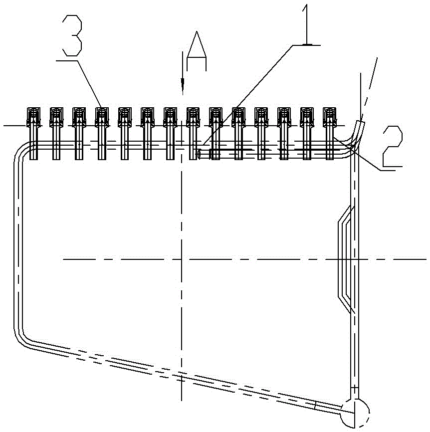
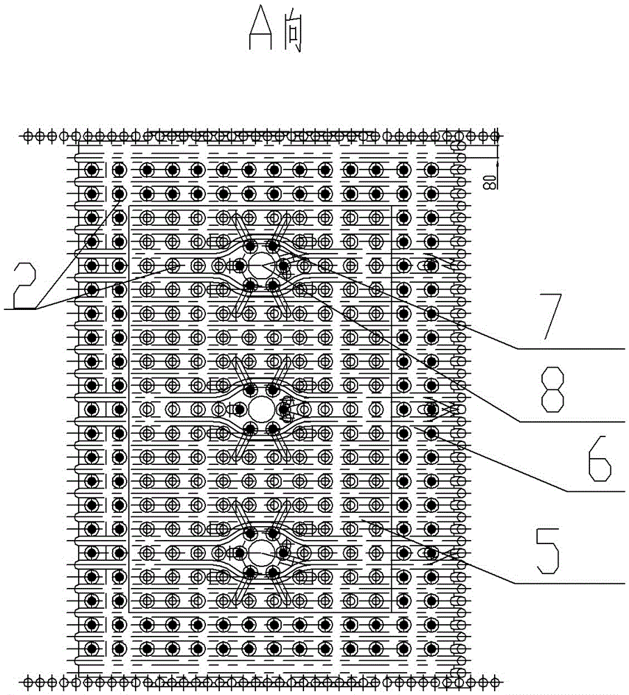
[0023] See figure 1 , figure 2 , image 3 As shown, an air distribution structure of a circulating fluidized bed boiler, which includes an air distribution plate 1, the air distribution plate 1 is installed with a connecting pipe 2 passing through the air distribution plate, the upper part of the connecting pipe 2 is equipped with a wind cap 3, and the connecting pipe 2 is provided with The opening 4 communicating with the wind cap 3, the air distribution plate 1 is divided into a central area 5 and a side wall area 6, the central area 5 is specifically a rectangular area, and the side wall area 6 is a rectangular frame area surrounding the central area 5, located on the side The opening ratio on the connecting pipe 2 of the wall area 6 is greater than the opening ratio on the connecting pipe 2 located in the central area 5; only. The connecting pipe 2 communicates with the air cap 3 through the opening 4, and the air outlet hole is arranged on the air cap 3, and the air e...


PUM


Abstract

The invention relates to the technical field of circulating fluidized bed boilers, in particular to an air distribution structure of a circulating fluidized bed boiler. By adoption of the air distribution structure of the circulating fluidized bed boiler, uniform fluidization of a bed layer can be achieved, the combustion efficiency is improved, and safe operation of the boiler is guaranteed. The air distribution structure of the circulating fluidized bed boiler comprises an air distribution plate. Connecting pipes penetrating through the air distribution plate are mounted on the air distribution plate. Air caps are mounted on the upper sections of the connecting pipes. Holes communicating with the air caps are formed in the connecting pipes. The air distribution structure of the circulating fluidized bed boiler is characterized in that the air distribution plate is divided into a central area and an edge wall area, and the edge wall area surrounds the central area; the aperture ratio of the portion, located in the edge wall area, of each connecting pipe is larger than that of the portion, located in the central area, of the connecting pipe; hole areas are arranged in the central area; each hole area comprises a slag falling pipe, and connecting pipes which are the same as the connecting pipes in the edge wall area are arranged around each slag falling pipe.

Description

technical field [0001] The invention relates to the technical field of circulating fluidized bed boilers, in particular to an air distribution structure of circulating fluidized bed boilers. Background technique [0002] As an advanced coal-fired technology, circulating fluidized bed combustion technology has the advantages of good fuel adaptability, high efficiency, and less pollution emissions, and is widely used in power plant boilers and industrial boilers. [0003] The air distribution device is one of the key components in the combustion equipment of the circulating fluidized bed boiler. Its performance directly affects the fluidization status of the fluidized bed boiler and the flow, combustion and heat transfer process in the combustion chamber, which in turn affects the fluidized bed boiler. performance. [0004] Among them, the fluidization method is: the air required for combustion enters the fuel bed from bottom to top through the air distribution plate at the b...

Claims


Application Information

Patent Timeline
Patent Type & Authority Applications(China)
IPC IPC(8): F23C10/20F23C10/00
CPCF23C10/20F23C10/002F23C2206/101
Inventor 夏胜陆晓焰杨巍钱钢
Owner WUXI HUAGUANG BOILER
Why Eureka
Eureka Blog
Learn More