A method for replacing movable pulley blocks in bridge cranes

A technology of bridge cranes and movable pulley blocks, which is applied to the direction of traveling bridge cranes, cranes, load blocks, etc., and can solve the problems of short replacement operation time, reduced operation intensity, and high work intensity, and achieves short replacement operation time and reduced The effect of increasing work intensity and improving work efficiency

Active Publication Date: 2016-09-28
SHANDONG IRON & STEEL CO LTD
View PDF5 Cites 0 Cited by
  • Summary
  • Abstract
  • Description
  • Claims
  • Application Information

AI Technical Summary

Problems solved by technology

[0006] The purpose of the present invention is to solve the technical problems of high work intensity, long replacement time and low work efficiency caused by the existing method for replacing the movable pulley block of bridge crane; to provide a method for replacing the movable pulley block of bridge crane. Using this method, the replacement of the movable pulley block can be completed without replacing the steel wire rope, and the replacement operation time is short, which greatly reduces the operation intensity, reduces the workload of the workers, and improves the operation efficiency

Method used


Image

  • A method for replacing movable pulley blocks in bridge cranes
  • A method for replacing movable pulley blocks in bridge cranes

Examples


Embodiment 1

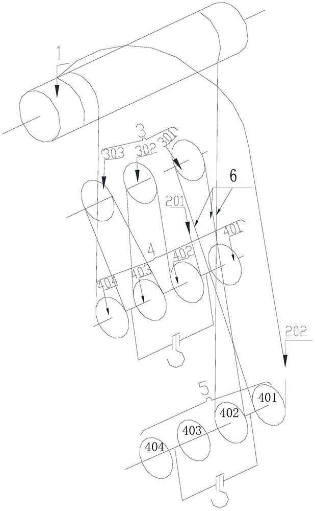
[0040] Such as figure 2 As shown, in this embodiment, using the above-mentioned method for replacing the movable pulley block in the bridge crane, replacing the movable pulley block with four movable pulleys includes the following steps:

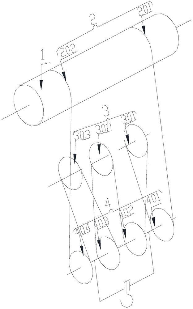
[0041] Step 101) Remove the limit switch (not shown) on the reel 1, lower the old movable pulley block 4 wound on the wire rope to the work area, and place the old movable pulley block 4 and the replaced new movable pulley block 5 side by side;

[0042] Step 102) Put down all the wire ropes 2 wound on the reel 1 until the two ends of the wire ropes are pressed by the pressure plate (not shown) and remain on the reel 1, remove the pressure plate at one end of the reel 1, and Strip the exposed first rope end 201 from the reel 1 and place it on the ground;

[0043] Step 103) Rotate the reel 1 in the forward direction, so that the other end of the reel 1 is wound with the steel wire rope 2 and continues to be wound on the reel 1, and the first...


PUM


Abstract

The invention provides a method for replacing a movable pulley block in a bridge crane. According to the method, an original steel wire rope is separated from an original movable pulley block and is wound on another movable pulley block for replacement by connecting and adjusting a nylon rope between each fixed pulley and the corresponding movable pulley, so that the replacement operation of the movable pulley block in the bridge crane is completed, and by comparison of an existing movable pulley block replacement method of the bridge crane, the replacement operation time is shortened, the operation strength is greatly reduced, the workload of workers is reduced, and the operation efficiency is improved.

Description

technical field [0001] The invention belongs to the technical field of bridge crane equipment installation, and in particular relates to a method for replacing a moving pulley block in a bridge crane. Background technique [0002] The state of use of the bridge crane motor pulley block in the prior art is as follows: figure 1 As shown, at first, the first rope end 201 of the steel wire rope 2 is fixed on the reel 1 through the pressing plate (not shown), a part of the steel wire rope 2 is wound on the reel 1, and then the second rope end 202 is passed through in turn. The first movable pulley 401 on the old movable pulley block 4, the first fixed pulley 301 on the fixed pulley block 3, the second movable pulley 402 on the old movable pulley block 4, the second fixed pulley 302 on the fixed pulley block 3, and the old movable pulley block 4 The third movable pulley 403, the third fixed pulley 303 on the fixed pulley block 3 and the fourth movable pulley 404 on the old movabl...

Claims


Application Information

Patent Timeline
Patent Type & Authority Patents(China)
IPC IPC(8): B66C11/16B66D3/06
CPCB66C17/00B66D3/06
Inventor 王光成刘喆
Owner SHANDONG IRON & STEEL CO LTD
Why Eureka
Try Eureka