Air flow through control valve

A technology for regulating valves and airflow, which is applied to components of pumping devices for elastic fluids, liquid variable-capacity machines, and variable-capacity pump components. It can solve problems such as poor sealing, complex structures, and high production costs. Good sealing, stable gas flow, and reduced production difficulty

Inactive Publication Date: 2017-01-04
阜宁优越机械有限公司
View PDF7 Cites 0 Cited by
  • Summary
  • Abstract
  • Description
  • Claims
  • Application Information

AI Technical Summary

Problems solved by technology

[0003] The technical problem to be solved by the present invention is that the existing pneumatic diaphragm pump regulating valve has complex structure, high production cost and poor sealing performance

Method used


Image

  • Air flow through control valve
  • Air flow through control valve
  • Air flow through control valve

Examples


Embodiment Construction

[0031] The following describes the technical solutions in the embodiments of the present invention clearly and completely with reference to the accompanying drawings in the embodiments of the present invention. Obviously, the described embodiments are only a part of the embodiments of the present invention, not all the embodiments. Based on the embodiments of the present invention, all other embodiments obtained by those of ordinary skill in the art without creative work shall fall within the protection scope of the present invention.

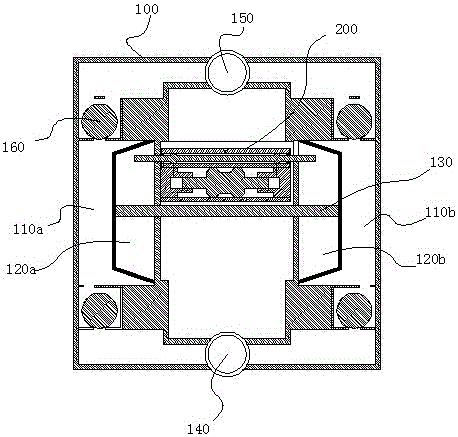
[0032] Such as Figure 1-7 As shown, the present invention provides a leak-proof pneumatic diaphragm pump, which includes a pump body 100. The upper and lower ends of the pump body 100 are respectively provided with a water outlet tee 150 and a water inlet tee 140. The left end of the pump body 100 and The right end is respectively provided with a left liquid chamber 110a and a right liquid chamber 110b communicating with the water outlet tee 150 ...


PUM


Abstract

The invention discloses an air flow penetrating type regulating valve which comprises a valve sleeve and a partition plate. The partition plate is arranged in the valve sleeve, an inner cavity of the valve sleeve is divided into a main controlling cavity and a regulating cavity by the partition plate, an air inlet groove is formed in the middle of the outer wall of the valve sleeve, a left air groove and a right air groove which are symmetrical with each other are formed in the two sides of the air inlet groove, the left air groove and the right air groove are respectively communicated with air chambers of corresponding lateral edges, and a left air exhausting groove and a right air exhausting groove which are symmetrical with each other are respectively formed in the outmost side. Air holes communicated with the main control cavity are respectively formed in the bottoms of the air inlet grooves, the left air groove, the right air groove, the left air exhausting groove and the right air exhausting groove; a central venting hole communicated with the main control cavity and the regulating cavity is formed in the middle of the partition plate; and a third venting hole and a fourth venting hole which are symmetric with each other are respectively formed in the two sides of the central venting hole.

Description

Technical field [0001] The invention relates to an airflow penetrating control valve of a pneumatic diaphragm pump. Background technique [0002] Through searching, the applicant found a pneumatic diaphragm pump (patent number: 2012101329572) applied by the applicant Anhui Lechang Pneumatic Fluid Equipment Technology Co., Ltd., which discloses a product similar to the oxygenator of the present invention, which uses air source to generate The air pressure is used as power to drive the left and right reciprocating movement of the diaphragm; it sleeves the spool shaft (equivalent to the control shaft of the present invention) in the central spool. Both ends of the central spool are provided with step cavities, and the end spools The inner end surface is provided with a secondary annular step; the structure of the center valve core and the end valve core is complicated, which increases the production cost. Summary of the invention [0003] The technical problem to be solved by the pr...

Claims


Application Information

Patent Timeline
Patent Type & Authority Patents(China)
IPC IPC(8): F04B53/10F04B43/073
Inventor 陆秀尧朱盛
Owner 阜宁优越机械有限公司
Why Eureka
Try Eureka