Threaded self-locking quick release device

A disengagement device and self-locking technology, which is applied in the field of threaded self-locking quick release devices, can solve the problems of complex safety, inconvenient, poor portability, etc., and achieve the effect of low cost, simple structure and convenient operation

Active Publication Date: 2018-05-04
锦州市特种设备监督检验所
View PDF9 Cites 0 Cited by
  • Summary
  • Abstract
  • Description
  • Claims
  • Application Information

AI Technical Summary

Problems solved by technology

[0002] The present invention aims to solve the problems of power-off fall and hydraulic leakage, as well as complex operation, poor safety, and inconvenient carrying in previous experiments. Affected by external power outages, it can be remotely operated by electric control to avoid the danger caused by manual operation at the falling site. It has a simple structure, low cost, convenient operation, and is safe and reliable.

Method used


Image

  • Threaded self-locking quick release device
  • Threaded self-locking quick release device
  • Threaded self-locking quick release device

Examples


Embodiment Construction

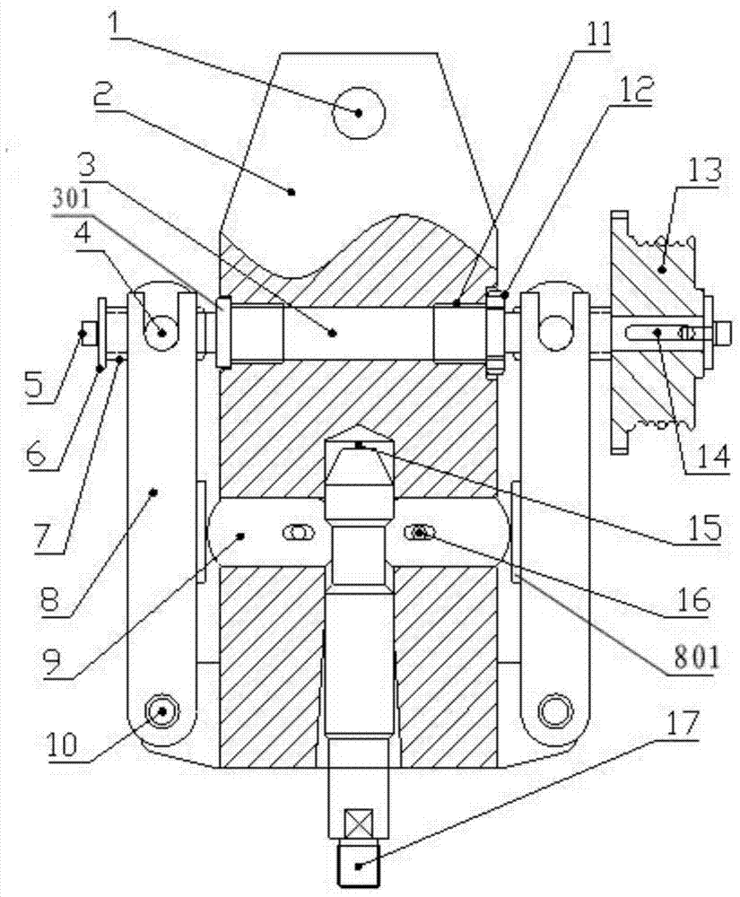
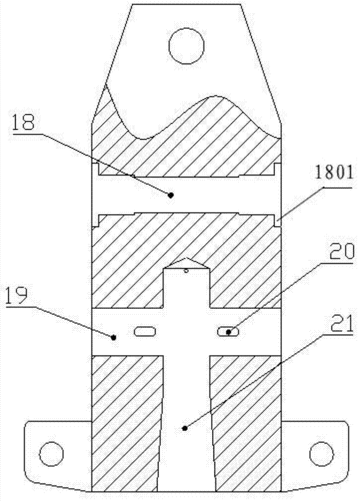
[0025] The threaded self-locking quick release device includes a lock body 2 and a lock head 17. The top of the lock body 2 is provided with a hoisting hole 1, and the bottom is provided with a vertical cavity 21 for inserting the lock head 17. The bottom of the vertical cavity 21 is The expanded shape of the horn is convenient for the lock head 17 to enter the vertical cavity 21 during automatic clamping; the lock head 17 is inserted in the vertical cavity 21 from bottom to top and a vent hole 15 is formed on the top of the vertical cavity 21, when the lock When the head 17 is inserted into or removed from the vertical cavity 21, positive pressure or negative pressure can be avoided.

[0026] The middle part of the lock body 2 is provided with a lower radial through hole 19 communicating with the vertical cavity 21, and the plug-in lock head 17 corresponding to the lower radial through hole 19 has a reduced diameter, and the lower radial through hole 19 is provided with a lock...


PUM


Abstract

A threaded self-locking quick release device capable of simulating falling from a broken rope, not affected by external power outages, capable of remote electric control operation, simple in structure, low in cost, convenient in operation, safe and reliable, with a vertical cavity at the bottom of the lock body , the lock head is inserted into the vertical cavity, and the middle part of the lock body is provided with a lower radial through hole. The positioning pin is positioned, and the inner end of the locking block is provided with a protrusion; the upper part of the lock body is provided with an upper radial through hole, and a screw drive shaft is inserted in the upper radial through hole, and a sliding bearing is installed on the screw drive shaft. The two ends of the shaft are provided with positive and negative trapezoidal threads and nuts, and the right end of the screw drive shaft is equipped with a driving wheel and a baffle II; both sides of the lock body are equipped with a fork locking arm, and the fork locking arm The bottom is hinged on the lock body, the forks of the two locking arms of the shift fork are respectively inserted into the protruding cylinders on the front and rear sides of the two nuts, and the inner side of the middle part of the locking arms of the shift fork is provided with a protruding top platform.

Description

Background technique [0001] With the acceleration of urbanization and the rapid pace of urban construction, there are more and more high-rise buildings in cities and towns, and the vertical lifting equipment used in these places is increasing significantly. Due to the increase in the number of vertical lift equipment, the related fall accidents are also constantly occurring, and there is an increasing trend with the increase of the service life of the equipment. There are great hidden dangers in vertical lifting equipment. According to statistics, in recent years, there have been many vertical lifting equipment falling accidents in my country that caused mass casualties and injuries, causing losses of hundreds of millions of yuan every year. The drop test to ensure the safety of vertical lifting equipment has become an important matter related to public safety production. At present, there are three commonly used disengagement methods in the drop test and vertical impact tes...

Claims


Application Information

Patent Timeline
Patent Type & Authority Patents(China)
IPC IPC(8): G01M99/00G01M7/08
Inventor 刘大卫孔英姿元智伟常艺萱
Owner 锦州市特种设备监督检验所
Why Eureka
Try Eureka