Panel lightspot detection method and system

A detection method and technology of a detection system, applied in the detection field, can solve problems such as the inability of detection personnel to distinguish bright spots and high brightness

Active Publication Date: 2015-07-29
UTECHZONE CO LTD
View PDF5 Cites 6 Cited by
  • Summary
  • Abstract
  • Description
  • Claims
  • Application Information

AI Technical Summary

Problems solved by technology

[0003] However, in the prior art, if there are foreign objects such as particles or dust on the surface of the panel, if light penetrates the panel, the foreign objects may reflect the light and cause the captured image to reflect that the brightness of the foreign objects is higher than that of the surrounding area. cause misjudgment
In this case, inspectors cannot distinguish which bright spots in the image are caused by bright spots and which bright places are caused by foreign objects on the surface

Method used


Image

  • Panel lightspot detection method and system
  • Panel lightspot detection method and system
  • Panel lightspot detection method and system

Examples


Embodiment Construction

[0028] The present invention will be described in detail below in conjunction with the accompanying drawings and embodiments.

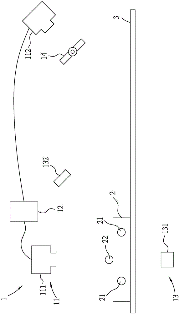
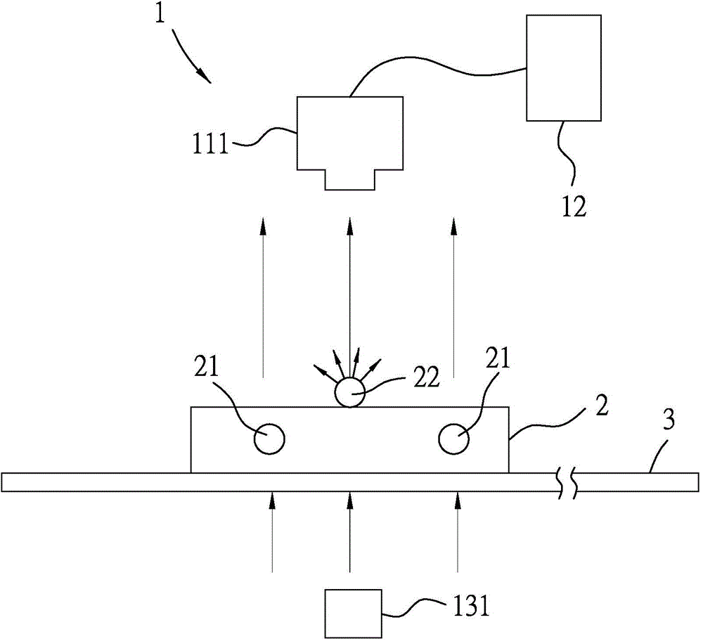
[0029] refer to figure 1 , a preferred embodiment of the panel bright spot detection method of the present invention is executed by a panel bright spot detection system 1 and is suitable for testing a panel 2 . The panel bright spot inspection system 1 includes an image capturing module 11 , a processing module 12 , a light source module 13 , and a polarizer 14 connected thereto. The light source module 13 includes a transmission light source 131 and a reflection light source 132, and the imaging module 11 includes a first imaging unit 111 matching the transmission light source 131 and a second imaging unit 112 matching the reflection light source 132. An image capturing unit 111 and a second image capturing unit 112 are respectively a line-scan camera with a photosensitive coupling element and a lens, both of which capture images in a line-scan mann...


PUM


Abstract

The invention provides a panel lightspot detection method and a system, used for detecting the lightspot defect of a panel. According to the method, an image acquiring module acquires a transmitted image on behalf of a lightspot defect and a foreign matter. Meanwhile, the image acquiring module acquires a reflected image. In the reflected image, the part of a higher brightness is formed through a polarizer when the light is reflected by the foreign matter on the panel. The reflected light is in the form of the linearly polarized light polarized along a first direction when no foreign matter exists on the panel. The polarizer is provided with an optical axis and the optical axis is vertical to the first direction so as to block the linearly polarized light. A processing module conducts the image subtraction operation. That means, all pixel values of the transmitted image are subtracted by all pixel values of the reflected image to form a result image. In the result image, the part of the higher brightness is just the location of the lightspot defect.

Description

technical field [0001] The invention relates to a detection method, in particular to a detection method and system for panel bright spots. Background technique [0002] There is a panel bright spot detection technology that utilizes transmitted light combined with image recognition for detection; that is, light is illuminated from one side of a panel, and an image is captured from the other side. If the panel has an internal defect that causes a bright spot, the internal defect cannot block light from passing through, while other normal parts block the light, the brightness of the corresponding defect in the captured image will be higher than that of the surrounding area, thereby detecting Panel highlights. [0003] However, in the prior art, if there are foreign objects such as particles or dust on the surface of the panel, if light penetrates the panel, the foreign objects may reflect the light and cause the captured image to reflect that the brightness of the foreign obj...

Claims


Application Information

Patent Timeline
Patent Type & Authority Applications(China)
IPC IPC(8): G01N21/88
Inventor 邓亦书
Owner UTECHZONE CO LTD
Why Eureka
Try Eureka