
Amplitude modulation circuit, signal transmission circuit and card reader

A modulation signal and amplitude modulation technology, applied in the fields of signal transmission circuits, card readers, and amplitude modulation circuits, can solve the problems of reducing the accuracy of modulation coefficients, and achieve the effect of high accuracy

Active Publication Date: 2017-03-22
KTMICRO ELECTRONICS
View PDF8 Cites 0 Cited by
  • Summary
  • Abstract
  • Description
  • Claims
  • Application Information

AI Technical Summary

Problems solved by technology

[0003] However, in the process of actually implementing amplitude modulation, the accuracy of the modulation coefficient will be reduced due to factors such as the distance between the card reader antenna and the RFID tag, and current changes.

Method used


Image

  • Amplitude modulation circuit, signal transmission circuit and card reader
  • Amplitude modulation circuit, signal transmission circuit and card reader
  • Amplitude modulation circuit, signal transmission circuit and card reader

Examples


Embodiment Construction

[0035] The present invention will be further described below in conjunction with the accompanying drawings and specific embodiments.

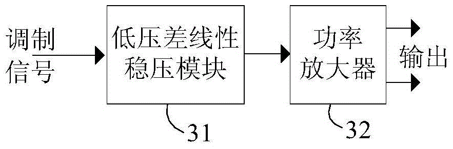
[0036] Such as image 3 Shown is a schematic structural diagram of the first embodiment of the amplitude modulation circuit of the present invention, the circuit may include: a low dropout linear voltage regulator module 31 and a power amplifier 32, and the low dropout linear voltage regulator module 31 is connected to the power amplifier 32.

[0037] In this embodiment, the low dropout linear voltage regulator module 31 is used to generate an output voltage according to the modulation signal; the power amplifier 32 is used to use the above output voltage as a power supply voltage to generate and output a modulated signal. Here, the modulation signal can be controlled and input by an external controller, and the modulation signal can be a control signal for amplitude modulation of a specific modulation coefficient, for example: an amplitude mod...


PUM


Abstract

The invention relates to an amplitude modulation circuit, a signal emission circuit and a card reader. The amplitude modulation circuit comprises a low drop-out linear voltage regulator module and a power amplifier, wherein the low drop-out linear voltage regulator module is used for generating output voltage according to a modulating signal, and the power amplifier is used for adopting the output voltage as supply voltage as well as generating and outputting a modulated signal. The invention is used for accurately realizing the amplitude modulation of specific modulation factors, the modulation factors are not influenced by current and the like and the accuracy is high.

Description

technical field [0001] The invention relates to the field of electronic circuits, in particular to an amplitude modulation circuit, a signal transmitting circuit and a card reader. Background technique [0002] In modulation technology, modulation factor is an important parameter. For example: in the communication process between the card reader and the radio frequency identification (radio-frequency identification, referred to as: RFID) tag, the carrier of the card reader is 13.56MHz, and the data to be transmitted by the card reader passes through a certain data rate and is amplitude-modulated The mode modulation transmits to the RFID tag on the carrier, and the data rate can be: 106kbit / s, 212kbit / s, 424kbit / s and 848kbit / s; the RFID tag transmits data to the card reader through load modulation. The data rate, modulation method, and modulation waveform of the communication between the card reader and the RFID tag need to meet the requirements of standards such as ISO / IEC...

Claims


Application Information

Patent Timeline
Patent Type & Authority Patents(China)
IPC IPC(8): G05F1/56
Inventor 张利杜洪立杨培
Owner KTMICRO ELECTRONICS
Learn More