
Method for realizing perfectly matched layer by using current density convolution in plasma

A completely matching layer and plasma technology, applied in the field of computational electromagnetics, can solve the problems of large memory consumption, unsatisfactory absorption effect, poor absorption effect, etc.

Active Publication Date: 2015-07-29
XIAN UNIV OF TECH
View PDF3 Cites 12 Cited by
  • Summary
  • Abstract
  • Description
  • Claims
  • Application Information

AI Technical Summary

Problems solved by technology

Someone proposed a perfectly matched layer (Perfectly matched layer, PML) absorption boundary. Later, PML was widely used to calculate the truncation of the area, and it was proved to be very effective. However, the research found that the traditional PML has an absorption effect on low frequencies and litter waves. Not ideal; using a PML (CFS-PML) absorption boundary with a complex frequency shift (CFS) factor can effectively improve the traditional PML's absorption effect for low frequencies, litter waves and glancing situations
Recently, someone proposed a WLP-FDTD method using an auxiliary differential equation that approximates a perfectly matched absorption boundary to solve the electromagnetic field problem in a dispersive medium. The absorption effect of this approximately perfectly matched absorption boundary is very poor, and there are errors in calculation. Moreover, this algorithm takes a long time to calculate and consumes a lot of memory.

Method used


Image

  • Method for realizing perfectly matched layer by using current density convolution in plasma
  • Method for realizing perfectly matched layer by using current density convolution in plasma
  • Method for realizing perfectly matched layer by using current density convolution in plasma

Examples


Embodiment Construction

[0057] The present invention will be described in detail below in conjunction with the accompanying drawings and specific embodiments.

[0058] A method of realizing the current density convolution complete matching layer in the plasma of the present invention, the principle is as follows: first derive Maxwell’s equations in the complex extended coordinate system satisfied by the electromagnetic field in the plasma, and then use a new high-speed and effective current The weighted Laguerre polynomial finite-difference time-domain method (JEC-WLP-FDTD) of density convolution derives the update equations of the electromagnetic field component coefficients and current densities in the entire calculation area, and finally uses the first equation of equation (15) to solve the observation The electromagnetic field component at the point.

[0059] When solving the updating equations satisfied by the propagation of electromagnetic waves in the plasma, it is first necessary to derive th...


PUM


Abstract

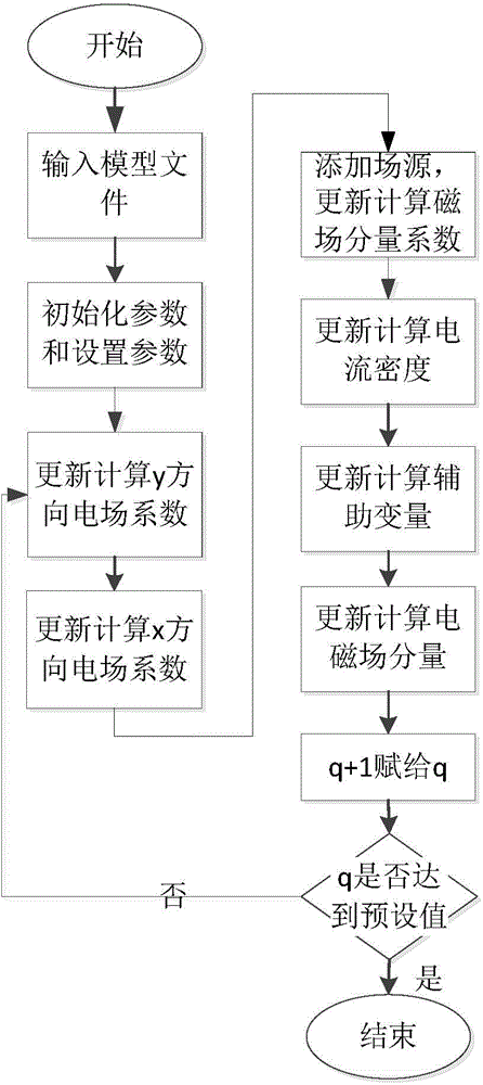
The invention discloses a method for realizing a perfectly matched layer by using current density convolution in a plasma. The method comprises the following steps of inputting a model file; initializing parameters and setting a PML (perfectly matched layer) coefficient and an absorbing boundary parameter; respectively updating and calculating the electric field component coefficients E<q>(y) and E<q>(x) of the whole calculation area in the y direction and the x direction, adding a field source to an electric field component coefficient, and updating and calculating the magnetic field component coefficient of the whole calculation area; updating and calculating the polarized current densities J<q>(x) and J<q>(y) of the whole calculation area, and updating and calculating the auxiliary variables of the electric and magnetic field component coefficients of the whole calculation area; updating and calculating electric and magnetic field components at an observing point; assigning q+1 assignment to q, judging whether step number q of Laguerre polynomials reaches a preset value or not, and if q does not reach the preset value, returning to step 3; if q reaches the preset value, ending. According to the method for realizing the perfectly matched layer by using the current density convolution in the plasma, the calculation speed is high, the memory consumption is low, and the method has very good absorbing effect on low frequencies and evanescent waves.

Description

technical field [0001] The invention belongs to the technical field of computational electromagnetics, and relates to a method for realizing a complete matching layer using current density convolution in plasma. Background technique [0002] The Finite-difference time-domain (FDTD) method is widely used in the simulation of electromagnetic wave propagation in dispersive media because of its simple implementation. However, its time step is limited by the Cauchy stability condition, which limits the application of the FDTD method to fine-structure models. In order to eliminate the limitation of the Cauchy stability condition, unconditionally stable finite-difference time-domain methods have been proposed, such as: Alternating-Direction-Implicit (ADI) finite-difference time-domain (ADI-FDTD) method and weighted-based Laguerre polynomials Finite-difference time-domain (WLP-FDTD) method. Among these methods, the ADI-FDTD method will produce a large dispersion error when using a...

Claims


Application Information

Patent Timeline
Patent Type & Authority Applications(China)
IPC IPC(8): G06F19/00
Inventor 席晓莉方云刘江凡
Owner XIAN UNIV OF TECH
Learn More