Intelligent automatic door as well as graph recognition unlocking method and automatic control method of intelligent automatic door

A graphic identification code and automatic door technology, applied in the field of security doors, can solve the problem of unsafe switch of chip card

Inactive Publication Date: 2015-07-29
李云祥
View PDF10 Cites 13 Cited by
  • Summary
  • Abstract
  • Description
  • Claims
  • Application Information

AI Technical Summary

Problems solved by technology

[0004] The invention is to solve the problem that the smart door adopts the chip card to realize the unsafe switch, and proposes the smart automatic door and its graphic recognition unlocking method and automatic control method

Method used


Image

  • Intelligent automatic door as well as graph recognition unlocking method and automatic control method of intelligent automatic door
  • Intelligent automatic door as well as graph recognition unlocking method and automatic control method of intelligent automatic door
  • Intelligent automatic door as well as graph recognition unlocking method and automatic control method of intelligent automatic door

Examples


specific Embodiment approach 1

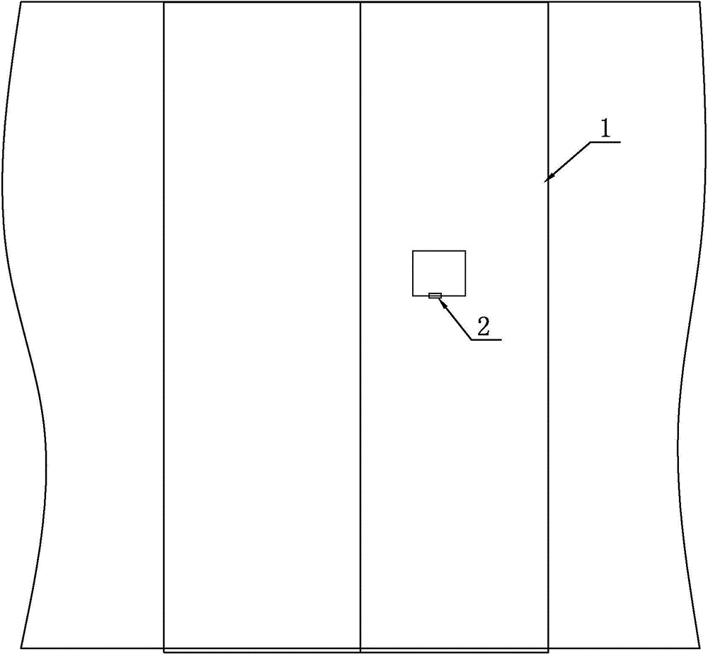
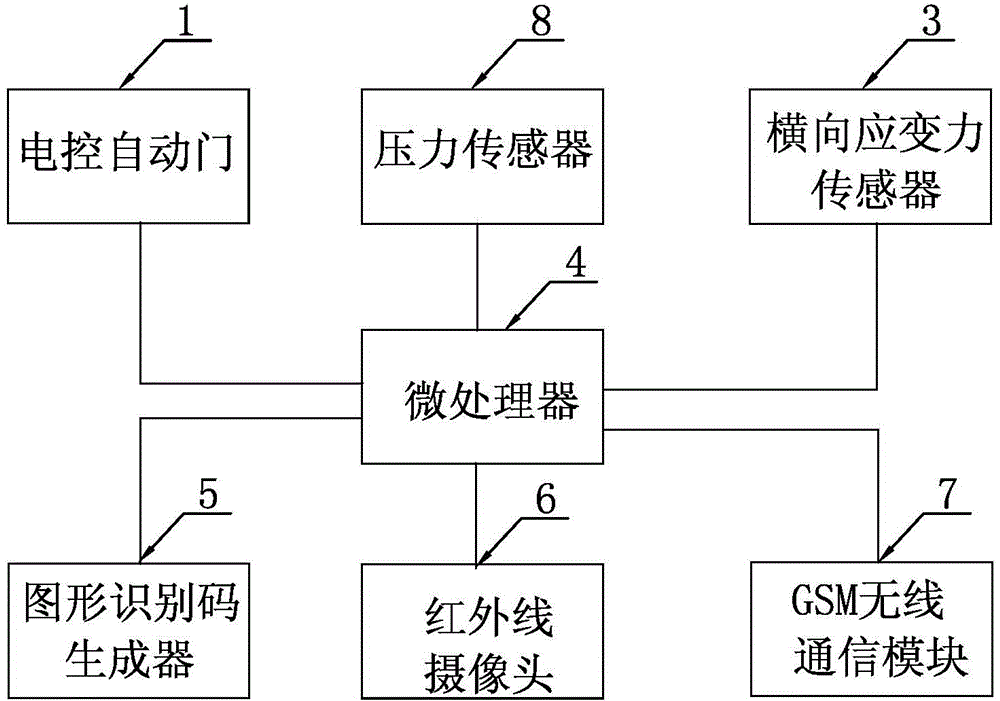
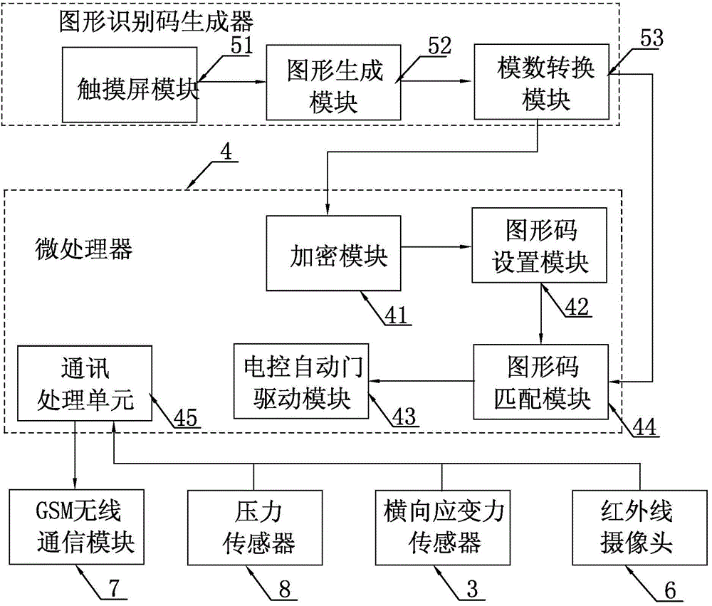
[0070] Specific implementation mode 1. Combination figure 1 figure 2 and image 3 Describe this embodiment, the intelligent automatic door described in this embodiment includes an electric control automatic door 1, it also includes an electric lock 2, a graphic identification code generator 5, a microprocessor 4, a lateral strain sensor 3, a pressure sensor 8 , GSM wireless communication module 7 and infrared camera 6;

[0071] There is a groove on the outside of the electric control automatic door 2, and the pattern identification code generator 5 is embedded in the groove, and the opening of the groove is covered with a baffle plate, and the gap between the baffle plate and the electric control automatic door 2 is There is an electric lock 2; the lateral strain sensor 3 and the pressure sensor 8 are respectively embedded and fixed on the outer surface of the electronically controlled automatic door 2, and the infrared camera 6 is installed on the outside of the electronic...

specific Embodiment approach 2

[0084] Specific embodiment two, combine Figure 4 Describe this embodiment, the difference between this embodiment and the intelligent automatic door described in Embodiment 1 is that it also includes No. 1 speaker 9, display 10, No. 2 speaker 11, No. 1 microphone 12, No. 2 microphone 13, electric Door switch button 14, doorbell button 15, doorbell 16, doorbell answer button 17 and multiple infrared sensors 18;

[0085] The doorbell button 15 is arranged on the outside of the electric control automatic door 2, the doorbell 16 is arranged on the inside of the electric control automatic door 2, a plurality of infrared sensors 18, No. 1 loudspeaker 9 and No. 1 microphone 12 outside the electric control automatic door 2, said The inner side of the electric control automatic door 2 is provided with a display 10, a No. 2 microphone 13, a No. 2 speaker 11 and an electric door switch button 14;

[0086] The No. 1 sound signal input end of the communication processing unit 45 is conne...

specific Embodiment approach 3

[0090] Specific embodiment three. This embodiment is different from the intelligent automatic door described in specific embodiment two in that it also includes an anti-theft device and a No. 2 infrared camera. The signal output end of the anti-theft device is connected to the alarm signal input end of the microprocessor 4, and the No. 2 infrared camera is installed on the inside of the electric control automatic door 2.

[0091] The anti-theft device described in this embodiment monitors the area near the electronically controlled automatic door, and can be used at night or when no one is at home. At the same time, the anti-theft device described in this embodiment can be connected to multiple detectors at the same time to change the detection range as needed. At the same time, when the anti-theft device detects an abnormality, the microprocessor drives the No. 2 infrared camera to start taking pictures, and sends the image signal captured by the No. 2 infrared camera to the m...


PUM


Abstract

The invention provides an intelligent automatic door as well as a graph recognition unlocking method and an automatic control method of the intelligent automatic door, and relates to the field of safety doors. With the adoption of the intelligent automatic door as well as the graph recognition unlocking method and the automatic control method of the intelligent automatic door, the problem that an intelligent door is unsafe to be locked and unlocked with a chip card is solved. A microprocessor is adopted to intelligently control the electrically-control automatic door, a graphic code is drawn through a graph recognition code recognizer, and accordingly, the problem that the chip card is prone to be stolen or the safety is low if a digital code is adopted is solved. A graph recognition code is adopted, a user can set the graph recognition code according to requirements of the user and can draw the graph recognition code during unlocking, the drawn code can be sent to the microprocessor, the microprocessor compares the received graph code with the set graph recognition code, and when the similarity is up to 90% or higher, the microprocessor sends an unlocking drive signal to the electrically-control automatic door. The user can also set a new graph recognition code before going out or set several graph recognition codes simultaneously, so that the graph recognition code is not prone to be revealed stolen, and the safety is high. The intelligent automatic door is applied to a safety door.

Description

technical field [0001] The invention relates to the field of security doors. Background technique [0002] Smart door refers to the anti-theft door that realizes many intelligent functions on the basis of the traditional anti-theft safety door through emerging technical means and the concept of the Internet of Things, with the host of the intelligent system as the carrier. [0003] In today's Chinese door industry market, higher-end smart doors have more intelligent functions, such as: on-site sound alarm function, remote automatic alarm function, one-key disarming and arming function, no power supply, signal transmission function, and arming when going out function, indoor defense function, theft scene monitoring function, door magnetic anti-prying function, tamper alarm function, host automatic reset function, multi-zone alarm prompt function, but the unique identification function of the chip, such a function can only be used for us sometimes. It brings great inconvenien...

Claims


Application Information

Patent Timeline
Patent Type & Authority Applications(China)
IPC IPC(8): G07C9/00
Inventor 李赞许建荣冯怡然高锐常迪李云祥
Owner 李云祥
Why Eureka
Try Eureka