Supercharge Your Innovation With Domain-Expert AI Agents!

X-ray CT device and control method

An X-ray and X-ray tube technology, applied in the field of X-ray CT devices, can solve the problems of undercounting characteristics and inability to separate photons

Active Publication Date: 2015-07-29
TOSHIBA MEDICAL SYST CORP
View PDF5 Cites 2 Cited by
  • Summary
  • Abstract
  • Description
  • Claims
  • Application Information

AI Technical Summary

Problems solved by technology

However, in photon counting CT, when the amount of incident radiation is large, the data counted for each photon is accumulated (piled up), and at this time, each photon cannot be separated, so undercounting occurs in which the counting characteristic is not linear.

Method used


Image

  • X-ray CT device and control method
  • X-ray CT device and control method
  • X-ray CT device and control method

Examples


no. 1 Embodiment approach

[0027] First, photon counting CT will be described before describing the X-ray CT apparatus according to the first embodiment.

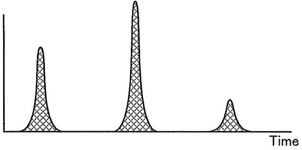
[0028] In photon counting CT, the amount of light (X-rays) is measured by counting the number of photons. The greater the number of photons per unit time, the stronger the light (X-rays). In addition, although individual photons have different energies, in photon counting CT, information on the energy components of X-rays can be obtained by measuring the energy of photons. That is, in photon counting CT, data collected by irradiating X-rays with one tube voltage can be divided into a plurality of energy components and imaged. For example, in photon counting CT, it is possible to obtain image data for identifying substances by utilizing the difference in K absorption limit.

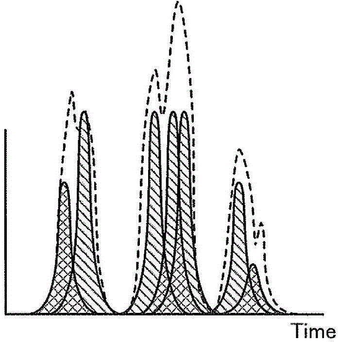
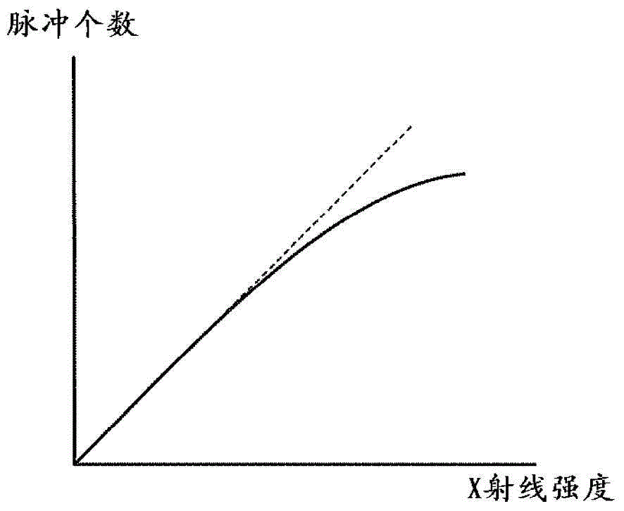
[0029] However, in photon counting CT, when the amount of incident radiation is large, "pile up" in which data counted by individual photons is accumulated occurs. When stacki...

no. 2 Embodiment approach

[0082] In the second embodiment, a case where the detector 13 is configured differently from the first embodiment will be described. In addition, the X-ray CT apparatus according to the second embodiment has the same configuration as the X-ray CT apparatus according to the first embodiment described using FIG. 1 except for the detector 13 .

[0083] In the detector 13 according to the second embodiment, the plurality of first elements 131 constituting the first element group and the plurality of second elements 132 constituting the second element group are two-dimensionally dispersed and arranged. Figure 8A as well as Figure 8B It is a figure for demonstrating an example of the detector concerning 2nd Embodiment. For example, if Figure 8A As shown, the first element 131 and the second element 132 are respectively arranged in an element row along the body axis direction in the detector 13 . and, if Figure 8A As shown, the element rows of the first element 131 and the el...

no. 3 Embodiment approach

[0089] In the third embodiment, for the case of performing the control process for reducing the radiation caused by the first scan, use Figure 9 Be explained. Figure 9 It is a figure for demonstrating the 1st scan concerning 3rd Embodiment.

[0090] In addition, the X-ray CT apparatus according to the third embodiment has the same configuration as the X-ray CT apparatus according to the first embodiment described with reference to FIG. The implementation is different. Hereinafter, the first scan performed in the third embodiment will be described.

[0091] The scan control unit 33 according to the third embodiment performs the first scan by irradiating the half circumference of the subject P with X-rays. That is, if Figure 9 As shown, the scan control unit 33 performs only X-ray irradiation in the range "from 0 degrees to 180 degrees". In other words, the first scan performed in the third embodiment is a half scan.

[0092] In addition, the scan control unit 33 accord...


PUM


Abstract

An X-ray CT device according to an embodiment comprises an intensity distribution data collection unit (14a), a scan control unit (33), a count result collection unit (14b) and an image reconstruction unit (36). The intensity distribution data collection unit (14a) collects, in a first scan, intensity distribution data of X-rays that are emitted from an X-ray tube (12) and penetrate a subject. The scan control unit (33) estimates the amount of X-rays for which individual X-ray photons that penetrate the subject can be distinguished on the basis of the intensity distribution data and irradiates the subject with the estimated amount of X-rays from the X-ray tube (12) to perform a second scan for a photon counting CT. The count result collection unit (14b) collects, in the second scan, the count results in which X-ray photons that are emitted from the X-ray tube (12) and penetrate the subject are counted. The image reconstruction unit (36) reconstructs X-ray CT image data on the basis of the count results.

Description

technical field [0001] Embodiments of the present invention relate to an X-ray CT apparatus and a control method. Background technique [0002] In recent years, an X-ray CT apparatus that performs photon counting CT (Computed Tomography) using a photon counting type detector has been developed. Unlike an integrating type detector used in a conventional X-ray CT apparatus, a photon counting detector outputs a signal capable of counting photons from X-rays transmitted through a subject. Therefore, in photon counting CT, an X-ray CT image with a high SN ratio (Signal per Noise) can be reconstructed. [0003] In addition, the signal output from the photon counting detector is used to measure (discriminate) the energy of each counted photon. Therefore, in photon counting CT, data collected by irradiating X-rays with one tube voltage can be divided into a plurality of energy components and imaged. For example, in photon counting CT, images of different identifiable substances u...

Claims


Application Information

Patent Timeline
IPC IPC(8): A61B6/03
CPCA61B6/542G06T2211/408G06T11/005A61B6/5205A61B6/032A61B6/4241A61B6/405A61B6/488A61B6/544A61B6/54A61B6/4233A61B6/4452A61B6/545A61B6/42A61B6/4208A61B6/482
Inventor 加藤彻中井宏章小渊宽太
Owner TOSHIBA MEDICAL SYST CORP
Features
  • R&D
  • Intellectual Property
  • Life Sciences
  • Materials
  • Tech Scout
  • Unparalleled Data Quality
  • Higher Quality Content
  • 60% Fewer Hallucinations
Learn More