Blender blade assembly and blender

A mixer and mixer tank technology, applied in chemical instruments and methods, mixers with rotary mixers, mixers, etc., to achieve improved mixing and mixing, optimized drag and lift, and superior mixing and the effect of mixing results

Inactive Publication Date: 2015-07-29
AB ELECTROLUX
View PDF5 Cites 3 Cited by
  • Summary
  • Abstract
  • Description
  • Claims
  • Application Information

AI Technical Summary

Problems solved by technology

Generally, this problem involves the accumulation of particulate matter under the mixer blades during operation

Method used


Image

  • Blender blade assembly and blender
  • Blender blade assembly and blender
  • Blender blade assembly and blender

Examples


Embodiment Construction

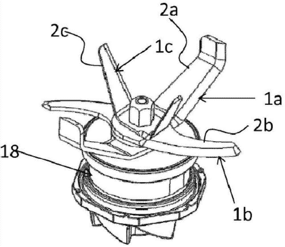
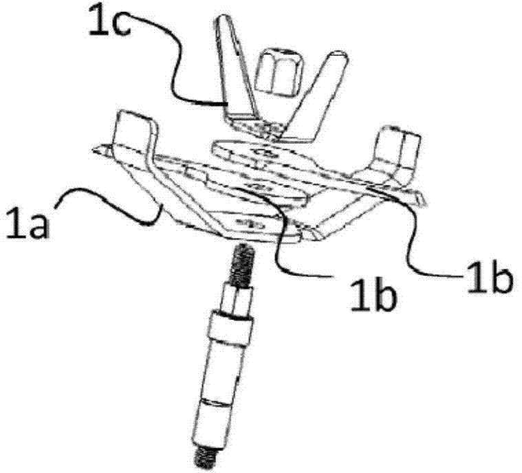
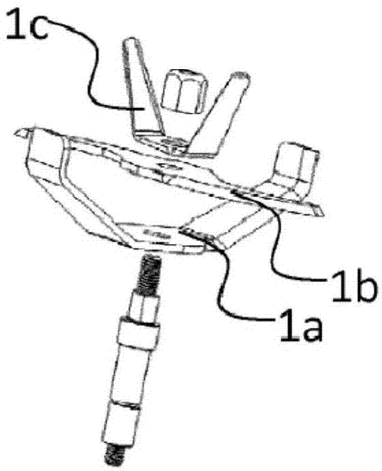
[0049] Figure 1a An embodiment of a blender blade assembly is shown. The vane assembly 18 includes a first vane 1a, referred to below Figure 3 to Figure 6 describe in detail. The first blade 1a has two symmetrical first blade arms 2a arranged for protruding outwards and upwards. The second blade 1b is arranged on top of the first blade 1a. The second blade is generally flat and has a curved profile (C-shape) on each second blade arm 2b. The C-shaped blades are tapered at the top. exist Figure 1b In the illustrated embodiment, the second blade 2a comprises two separate pieces or second blade arms 2b arranged on top of each other in the blade assembly, forming an S-shaped blade. In this way, a two-stage chopping or cutting area is produced. The second blade 1b can also be made of Figure 1c Manufactured from a single piece of material shown in . In the present embodiment, the second blade arms 2b are arranged opposite to each other on the same level. Typically, the C...


PUM


Abstract

The invention in particular is related to a to a blender blade assembly (18) having a first blade (1a) with two first blade arms (2a) extending from a centre plane (3) in opposite directions, wherein each blade arm (2a) comprises a planar base section (5) extending perpendicularly from the centre plane (3), wherein the base section (5) merges at its outer end (6) into a wing section (7) angled upwards from the base section (5), and wherein the blade assembly further comprises a second blade (1b) with two second blade arms (2b), wherein each second blade arm (2b) comprises a curve shaped blade.

Description

technical field [0001] The present invention is directed to a mixer blade assembly and a corresponding mixer. Background technique [0002] Blenders on the market today need to handle different ingredients and recipes and need to be able to liquefy, mix and produce different textures. In most cases, the performance of these mixers is measured in terms of final particle size after a certain period of processing. [0003] Thus, the circulation within the mixer tank and the efficiency of the blades arranged in the blade assembly have a lot to do with achieving good results. One of the most difficult tasks when processing food in a blender is having to process viscous ingredients or recipes such as smoothies, milkshakes or slushes due to the reduced circular motion and the power and Efficiency demands increase. The viscosity of such ingredients also reduces the suction effect carried by the vortices, and air pockets may form above the blades, causing them to spin without proc...

Claims


Application Information

Patent Timeline
Patent Type & Authority Applications(China)
IPC IPC(8): B01F7/02B01F7/04A47J43/07B01F7/00B01F13/10
CPCB01F7/021B01F7/04B01F2013/108B01F7/00166B01F13/1044A47J43/0722B01F7/00641B01F7/00275B01F27/07261B01F27/1123B01F27/192B01F27/61B01F27/70B01F33/8305B01F33/83611
Inventor E·达尔贝克M·罗哈斯·雷斯特雷波B·瓦因斯
Owner AB ELECTROLUX
Why Eureka
Try Eureka