Six-axis Swiss type milling machine tool

A machine tool, turning and milling technology, which is applied in the field of six-axis center turning and milling machine tools, can solve the problems that the forming time of tool workpieces is not well optimized and affects the forming efficiency of workpieces, and achieves the optimization of forming time, which is conducive to maintenance and optimization The effect of the work environment

Inactive Publication Date: 2015-08-05
NANJING JIANKE MACHINERY
View PDF8 Cites 0 Cited by
  • Summary
  • Abstract
  • Description
  • Claims
  • Application Information

AI Technical Summary

Problems solved by technology

[0004] The purpose of the present invention is to provide a six-axis center turning and milling machine tool to solve the problem that in the prior art, the tools on the center turning and milling machine are all installed on the same part, so each tool must wait for the previous one to work. The tool can only be processed after the tool is finished. The mutual limitation of the tool leads to the poor optimization of the workpiece forming time, which affects the technical defect of the forming efficiency of the workpiece.

Method used


Image

  • Six-axis Swiss type milling machine tool
  • Six-axis Swiss type milling machine tool
  • Six-axis Swiss type milling machine tool

Examples


Embodiment 1

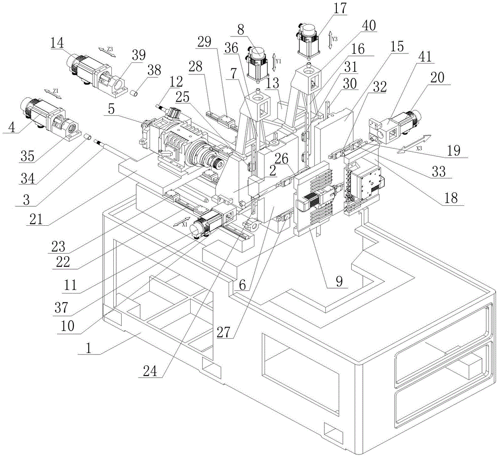
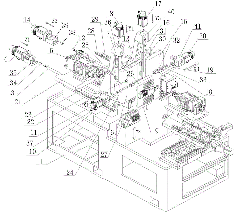
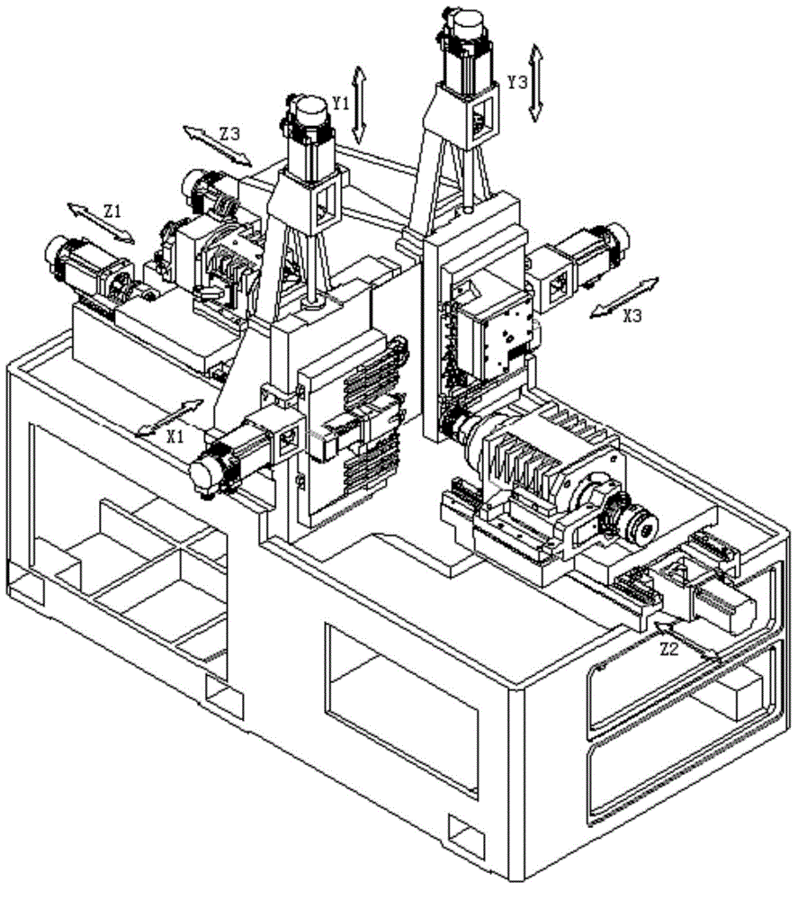
[0062] like figure 1 and figure 2 The shown positive axis includes a six-axis center turning and milling machine tool, including a bed 1, and a column 2 is set on the bed 1 and consists of a first column and a second column arranged along the X-axis direction. The X1 axis The positive axis group consisting of group, Y1 axis group, Z1 axis group and the third axis group composed of X3 axis group, Y3 axis group and Z3 axis group. The second column is provided with a through hole, and a guide sleeve or a structure without a guide sleeve is arranged in the through hole, which can be determined according to actual needs. In the present invention, the upright column can be fixed on the bed with bolts, or can be integrally formed with the bed when manufacturing the bed, and the positive axis group and the third shaft group are arranged side by side along the X-axis direction of the positive axis group. The same end of bed 1.

[0063]The Z1-axis group includes a Z1-axis slide plat...

Embodiment 2

[0075] The difference between the present invention and Embodiment 1 is that the first tool mounting seat 9 is the first turret, the second tool mounting seat 18 is the second turret, and the X1 axis slide block 27 that forms a sliding pair with the X1 axis rail 26 is arranged on the second turret. On the first turret, a tool is installed on the first turret; the X3-axis slider 33 that forms a sliding pair with the X3 axis rail 32 is arranged on the second turret, and a tool is installed on the second turret, and the rest of the structure is the same as that of the embodiment One is the same, see embodiment one for details, and will not be described in detail here.

Embodiment 3

[0077] The difference between this embodiment and Embodiment 1 is that the first tool mounting seat 9 is composed of an X1-axis slide plate and a first turret, and the X1-axis slide block 27 that forms a sliding pair with the Y1-axis rail 26 is installed on the X1-axis slide plate, The first turret is installed on the X3 axis slide plate; the second tool mounting seat 18 is composed of the X3 axis slide plate and the second turret, and the Y3 axis slide block 33 which forms a sliding pair with the X3 axis rail 32 is mounted on the X3 axis slide plate , the second turret is installed on the X3 axis slide plate. Knives are installed on the first turret and the second turret, and the rest of the structure is the same as that of Embodiment 1, and will not be described in detail here.


PUM


Abstract

The invention discloses a six-axis Swiss type milling machine tool. The six-axis Swiss type milling machine tool comprises a tool body (1), vertical columns (2) which are arranged on the tool body (1), a positive axis group which is arranged on the tool body (1) and formed by a X1 axis group, a Y1 axis group and a Z1 axis group and a third axis group which is formed by a X3 axis group, a Y3 axis group and a Z3 axis group; through holes are formed in the vertical columns (2); the positive axis group and the third axis group are arranged at the same end of the tool body (1) along the X axis direction of the positive axis group in parallel. The six-axis Swiss type milling machine tool has the advantages of overcoming the technical disadvantages that the forming efficiency of workpieces is influenced due to the facts that, in the prior art, cutting tools of the Swiss type milling machine tool are installed on the same part, every cutting tool can machine after the front cutting tool achieves machining, and the workpiece forming time is not well optimized due to mutual limit of the cutting tools.

Description

technical field [0001] The invention relates to a six-axis swivel-type turning and milling machine tool. Background technique [0002] In the existing centering machine market, there has been research on the technology of machine tool motion axes, and the most widely used is the three-axis centering machine with positive axis structure consisting of X1 axis group, Y1 axis group, and Z1 axis group. The Z1-axis slide plate of the three-axis centering machine has a machine tool main shaft. The machine tool main shaft is a through hole. The tail end of the machine tool main shaft is connected to the feeder. The workpiece material is placed on the feeder. After the worker edits the program, the feeder Continuously and uninterruptedly feed the material into the main spindle of the machine tool in sequence. The positive spindle of the machine tool clamps the bar and moves back and forth on the Z axis, and cooperates with the guide sleeve structure of the machine tool (the guide sle...

Claims


Application Information

Patent Timeline
Patent Type & Authority Applications(China)
IPC IPC(8): B23Q37/00B23Q1/01B23Q5/40B23P23/02
CPCB23Q37/00B23P23/02B23Q1/01B23Q5/40
Inventor 王建飞
Owner NANJING JIANKE MACHINERY
Why Eureka
Try Eureka