

Range hood capable of automatic cleaning
An automatic cleaning and range hood technology is applied in the directions of removing oil fume, cleaning methods and utensils, cleaning methods using tools, etc., can solve the problems of inconvenience, poor cleaning effect, complex self-cleaning function structure, etc., and achieves a simple structure. Novel, easy to use, high use value and market value effect
- Summary
- Abstract
- Description
- Claims
- Application Information
AI Technical Summary
Problems solved by technology
Method used
Image

Examples
Embodiment 1
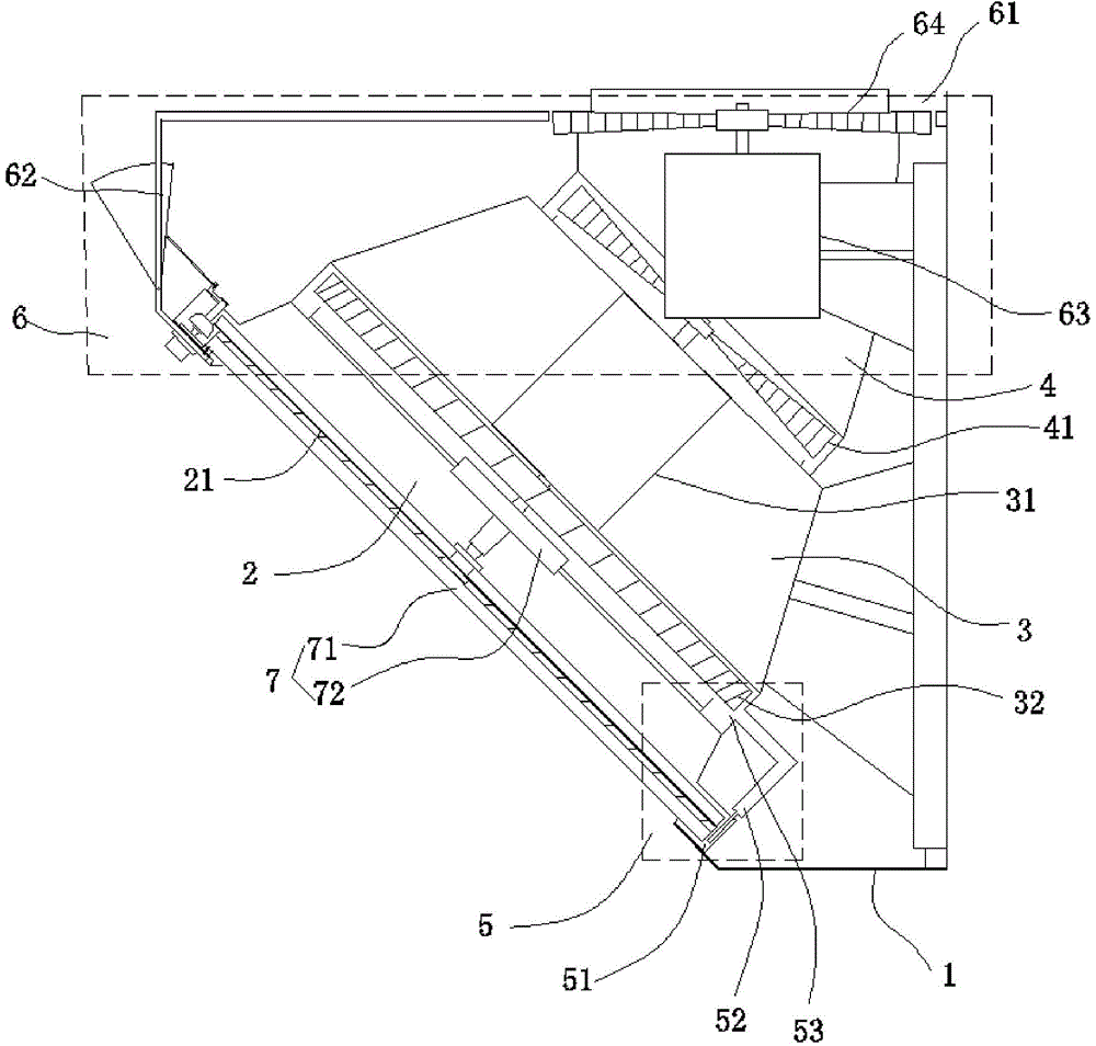
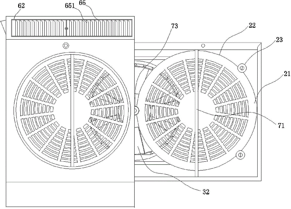
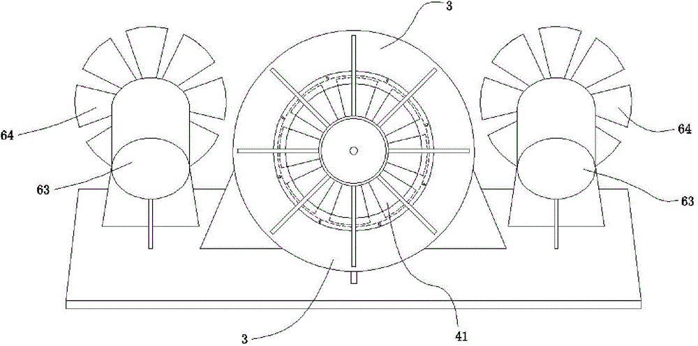
[0037] see Figure 1 to Figure 8 , a self-cleaning range hood of the present invention, comprising a casing 1, a main engine arranged in the casing 1 and separated from the inner cavity of the casing 1, the main engine includes a suction cavity 2 with a mesh plate 21, and is provided with an exhaust The motor 31 is connected to the blast chamber 3 driving the first impeller 32 , the exhaust chamber 4 connected to the blast chamber 3 and extending out of the casing 1 , the oil suction device 5 and the air supply device 6 . The air suction chamber 2 , the air blast chamber 3 and the air exhaust chamber 4 are sequentially connected and arranged in the host chamber, and the screen plate 21 is provided with an automatic cleaning device 7 .
[0038] Further, it also includes an annular groove 33 , which is arranged at the junction of the blast chamber 3 and the suction chamber 2 at the front end of the first impeller 32 , and the opening of the annular groove 33 faces the air inlet ...
Embodiment 2
[0051] like Figure 9 As shown, the automatic cleaning range hood of the second embodiment is roughly the same as that of the first embodiment, the difference being that the automatic cleaning device of the second embodiment includes a rotating scraper a71, a fixed screen a21 and a speed reducer a72. The scraper a71 is in contact with the screen a21, the exhaust motor shaft is connected to the first impeller and then connected to the reducer a72, the output shaft of the reducer is connected to the rotating scraper a71, and the opposite end of the rotating scraper a71 is connected to a scraper gear ring a74 , meshes with the driving gear a73, and the driving gear a73 drives the scraper a71 to rotate. In order to stabilize the rotation of the scraper a71, a stabilizer wheel a23 is provided on the edge of the scraper gear ring a74, and the stabilizer wheel a23 meshes with the scraper gear ring a74.
[0052] Alternatively, the output shaft of the reducer a72 passes through the me...
Embodiment 3
[0054] like Figure 10 , Figure 11 , Figure 12 , Figure 13 and Figure 14 As shown, Embodiment 3 is roughly the same as the automatic cleaning range hood in Embodiment 1. The difference is that in Embodiment 2, dual hosts b10 are arranged in b1 in the casing, and a blower motor b64 is arranged. The automatic cleaning device b7 includes a rotating Scraper b71, fixed mesh b21 and reducer b72. The scraper b71 is in contact with the screen b21, the exhaust motor b31 shaft is connected to the first impeller b32 and then extends into the suction chamber b2 to connect to the reducer b72, and the output shaft of the reducer b72 passes through the screen b21 to connect to the rotating scraper b71.
[0055] It also includes a lower air suction chamber b8 arranged below the air suction chamber b2, and the lower air suction chamber b8 communicates with the air suction chamber b2. The lower suction chamber b8 includes a fixed lower screen b81 and a rotating lower scraper b82, and t...
PUM
 Abstract
Description
Claims
Application Information